


SSI
ERP2U Power Supply Design Guide, V1.0
- 18 -
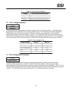
6.6 Dynamic Loading
STATUS
Required
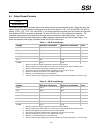
The output voltages shall remain within the limits specified in Table 13 for the step loading and within the limits
specified in Table 15 for the capacitive loading. The load transient repetition rate shall be tested between 50 Hz
and 5 kHz at duty cycles ranging from 10%-90%. The load transient repetition rate is only a test specification.
The ∆ step load may occur anywhere within the MIN load to the MAX load shown in Table 11.
Table 15: Transient Load Requirements
Output ∆ Step Load Size Load Slew
Rate
Capacitive Load
+3.3 V 30% of max load
0.5 A/µs 1,000 µF
+5 V 30% of max load
0.5 A/µs 1,000 µF
12V1+12V2+(12V3) 65% of max load
0.5 A/µs 1,000 µF
+5 VSB 25% of max load
0.5 A/µs 1 µF
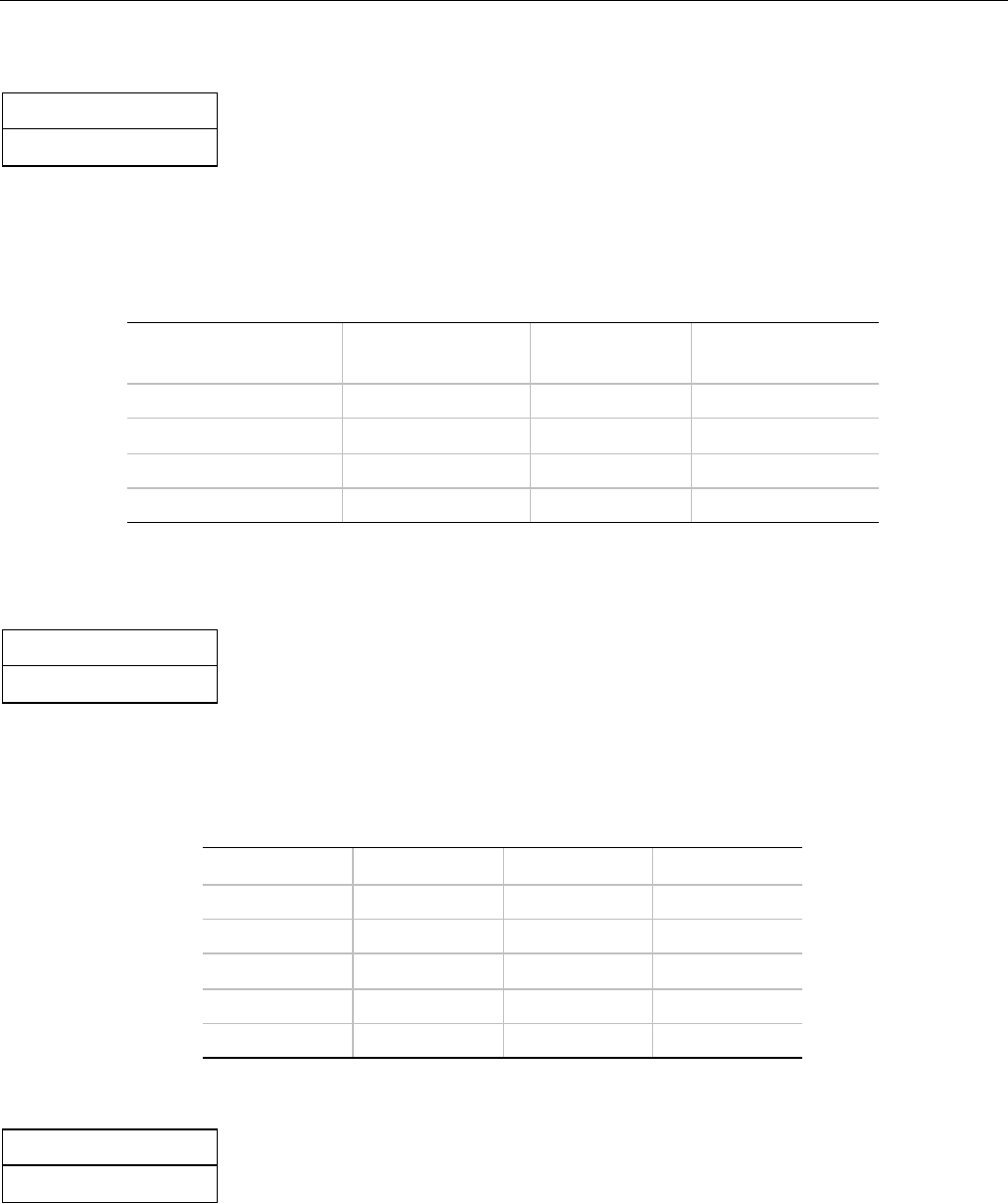
6.7 Capacitive Loading
STATUS
Required
The power supply shall be stable and meet all requirements, except dynamic loading requirements, with the
following capacitive loading ranges.
Note: Up to 10,000 µF of the +12V capacitive loading may be on the +12V1 output.
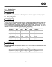
Table 16: Capacitve Loading Conditions
Output MIN MAX Units
+3.3 V 10 12,000
µF
+5 V 10 12,000
µF
+12 V 10 11,000
µF
-12 V 1 350
µF
+5 VSB 1 350
µF
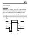
6.8 Ripple / Noise
STATUS
Required
The maximum allowed ripple/noise output of the power supply is defined in Table 17. This is measured over a
bandwidth of 0 Hz to 20 MHz at the power supply output connectors. A 10 µF tantalum capacitor in parallel with a
0.1 µF ceramic capacitor are placed at the point of measurement.