


Intel Desktop Board DH67GD Product Guide
46
Chassis Intrusion Header
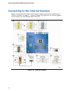
Figure 20, C shows the location of the chassis intrusion header. This header can be
connected to a mechanical switch on the chassis to detect if the chassis cover is
removed. This switch should be in the open position when the chassis cover is
installed and closed when the cover is removed.
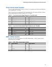
Table 8 shows the pin assignments and
signal names for
the chassis intrusion header.
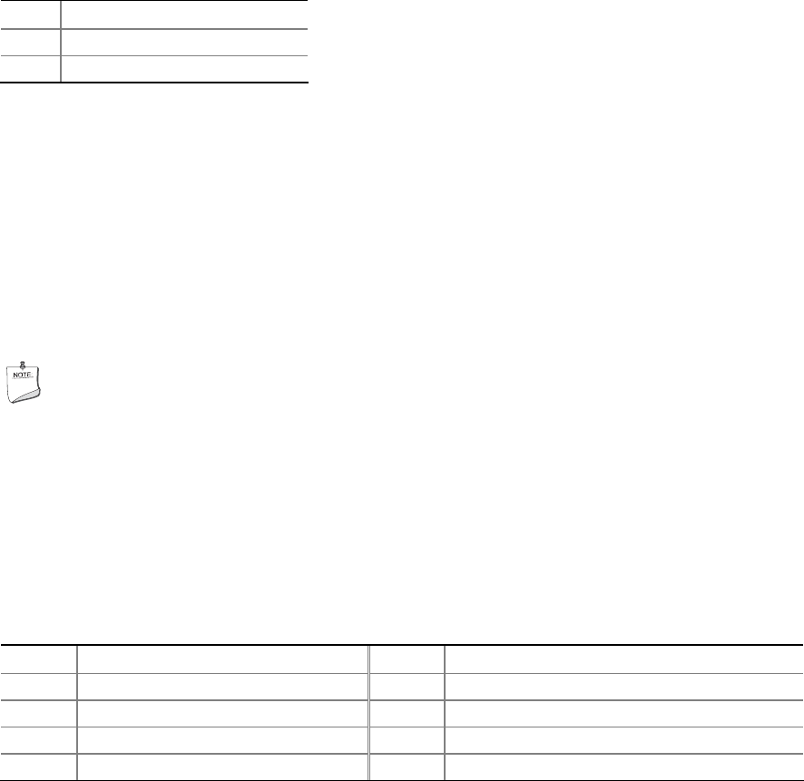
Table 8. Chassis Intrusion Header Signal Names
Pin Description
1 Ground
2 Intruder#
Consumer IR (CIR) Headers
The Desktop Board has two CIR headers: the receiver or input header (Figure 20, D)
and the output or emitter header (Figure 20, E). The receiver header consists of a
filt
ered translated infrared input compliant with Microsoft CIR specifications and a
“learning” infrared input. The learning input is a high-pass input which the computer
can use to “learn” to speak the infrared communication language of other user
remotes. The emitter header consists of two output ports which the computer can use
to emulate “learned” infrared commands in order to control external electronic
hardware.
NOTE
The Consumer IR option must be enabled in the system BIOS before it can
function. Press <F2> at boot to enter the system BIOS, and go to Advanced >
Peripheral Configuration > Enhanced Consumer IR, and set this option to
Enabled.
Table 9 shows the pin assignments for the front pa
nel
CIR receiver (input) header
and Table 10 shows the pin assignments for the back panel
CIR emitter (output)
header.
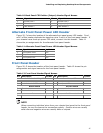
Table 9. Front Panel CIR Receiver (Input) Header Signal Names
Pin Signal Name Pin Signal Name
1 Ground 2 LED
3 No Connection 4 Learn-In
5 +5 V Standby 6 Vcc
7 Key (no pin) 8 CIR Input