


Intel Desktop Board DH67GD Product Guide
48
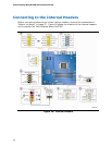
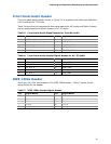
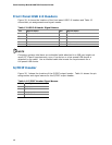
Front Panel USB 2.0 Headers
Figure 20, H shows the location of the front panel USB 2.0 headers and Table 13
shows their pin assignments and signal names.
Table 13. USB 2.0 Header Signal Names
Pin Signal Name Pin Signal Name
1 Power (+5 V) 2 Power (+5 V)
3 D- 4 D-
5 D+ 6 D+
7 Ground 8 Ground
9 Key 10 No Connection
NOTE
Computer systems that have an unshielded cable attached to a USB port might not
meet FCC Class B requirements, even if no device or a low-speed USB device is
attached to the cable. Use a shielded cable that meets the requirements for a
full-speed USB device.
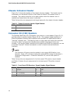
S/PDIF Header
Figure 20, I shows the location of the S/PDIF output header. Table 14 shows the pin
assignments and signal names for the S/PDIF output header.
Table 14. S/PDIF Header Signal Names
Pin Description
1 Ground
2 S/PDIF Out
3 Key (no pin)
4 +5 VDC