


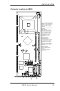
INSTALLATIONS
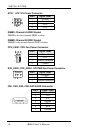
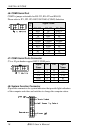
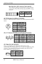
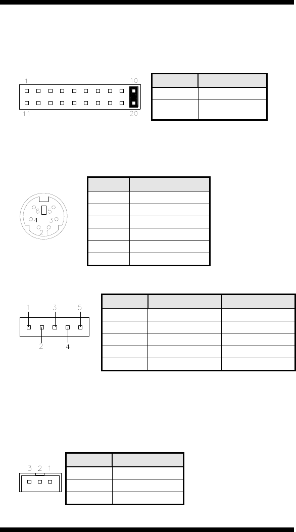
Hard Disk Drive LED Connector: Pins 10 and 20
This connector connects to the hard drive activity LED on
control panel. This LED will flash when the HDD is being
accessed.
Pin # Signal Name
10 HDD Active
20 5V
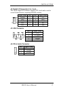
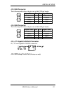
J9: PS/2 Keyboard and Mouse Connector
J9 uses a Y-cable with dual D-connectors for a PS/2 keyboard and a PS/2
mouse.
J9
Pin # Signal Name
1 Keyboard data
2 Mouse data
3 Ground
4 Vcc
5 Keyboard Clock
6 Mouse Clock
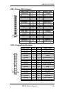
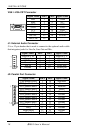
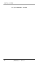
J10, J11: External PS/2 Mouse and Keyboard Connector
Pin # J10 J11
1 KB clock Mouse data
2 KB data N.C.
3 N.C. Ground
4 Ground Vcc
5 Vcc Mouse clock
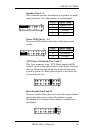
J12: Wake On LAN Connector
J12 is a 3-pin header for the Wake On LAN function on the
motherboard. The following table shows the pin out assignments of this
connector. Wake On LAN will function properly only with an ATX
power supply with 5VSB that has 1A.
Pin # Signal Name
1 +5VSB
2 Ground
3 LAN Wakeup
20 IB935 User’s Manual