


IM-Q35 Mainboard
2-14
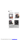
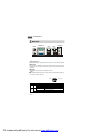
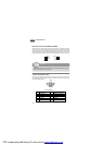
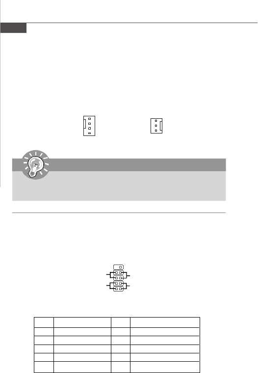
Fan Power Connectors: CPUFAN1, SYSFAN1
The fan power connectors support system cooling fan with +12V. When connecting
the wire to the connectors, always note that the red wire is the positive and should
be connected to the +12V; the black wire is Ground and should be connected to GND.
If the mainboard has a System Hardware Monitor chipset onboard, you must use a
specially designed fan with speed sensor to take advantage of the CPU fan control.
Important
Please refer to the recommended CPU fans at Intel
®
official website or consult
the vendors for proper CPU cooling fan.
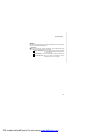
CPUFAN1
SENSOR
+12V
GND
CONTROL
SYSFAN1
SENSOR
+12V
GND
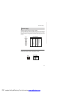
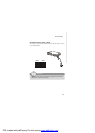
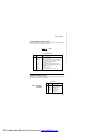
JFP1 Pin Definition
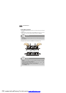
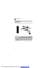
Front Panel Connector: JFP1
The mainboard provides one front panel connector for electrical connection to the
front panel switches and LEDs. The JFP1 is compliant with Intel
®
Front Panel I/O
Connectivity Design Guide.
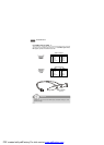
1
2
910
JFP1
HDD
LED
Reset
Switch
Power
LED
Power
Switch
+
+ +
-
--
PIN SIGNAL PIN SIGNAL
1 HDD LED+ 2 PWR LED+/PWR LED+
3 HDD LED- 4 PWR LED-/SLP LED+
5 RESET- 6 PWRBTN-
7 RESET+ 8 PWRBTN+
9 N/A 10 Key(no pin)
PDF created with pdfFactory Pro trial version www.pdffactory.com