


4-5
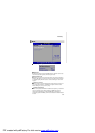
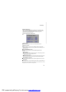
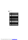
System Resources
Initialize the floppy controller in the super I/O. Some interrupt vectors
are initialized. DMA controller is initialized. 8259 interrupt controller is
initialized. L1 cache is enabled.
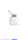
Set up floppy controller and data. Attem
pt to read from floppy.
Enable ATAPI hardware. Attempt to read from ARMD and ATAPI
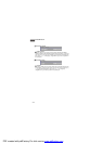
Disable ATAPI hardware. Jump back to checkpoint E9.
Read error occurred on media. Jump back to checkpoint EB.
defined recovery file nam
e in root directory.
Start reading FAT table and analyze FAT to find the clusters occupied
Start reading the recovery file cluster by cluster.
Check the validity of the re
covery file configuration to the current
configuration of the flash part.
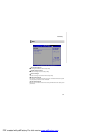
Make flash write enabled through chipset and OEM specific method.
Detect proper flash part. Verify that the found flash part size equals the
file size does not equal the found flash part size.
The flash has been updated successfully. Make flash write disabled.
Disable ATAPI hardware. Restore CPUID value back into register.
o F000 ROM at F000:FFF0h.
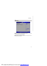
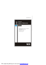
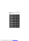
Checkpoint Description
03 Disable NMI, Parity, video for EGA, and DMA controllers. Initialize BIOS,
POST, Runtime data area. Also initialize BIOS modules on POST entry
and GPNV area. Initialized CMOS as mentioned in the Kernel Variable
"wCMOSFlags."
04 Check CMOS diagnostic byte to determine if battery power is OK and
CMOS checksum is OK. Verify CMOS checksum manually by reading
storage area. If the CMOS checksum is bad, update CMOS with power-on
default values and clear passwords. Initialize status register A.
Initializes data variables that are based on CMOS setup questions.
Initializes both the 8259 compatible PICs in the system
05 Initializes the interrupt controlling hardware (generally PIC) and interrupt
vector table.
06 Do R/W test to CH-2 count reg. Initialize CH-0 as system timer.Install the
POSTINT1Ch handler. Enable IRQ-0 in PIC for system timer interrupt.
Traps INT1Ch vector to "POSTINT1ChHandlerBlock."
07 Fixes CPU POST interface calling pointer.
08 Initializes the CPU. The BAT test is being done on KBC. Program the
keyboard controller command byte is being done after Auto detection of
KB/MS using AMI KB-5.
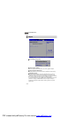
C0 Early CPU Init Start -- Disable Cache – Init Local APIC
C1 Set up boot strap processor Information
C2 Set up boot strap processor for POST
C5 Enumerate and set up application processors
C6 Re-enable cache for boot strap processor
C7 Early CPU Init Exit
0A Initializes the 8042 compatible Key Board Controller.
0B Detects the presence of PS/2 mouse.
0C Detects the presence of Keyboard in KBC port.
0E Testing and initialization of different Input Devices. Also, update the
Kernel Variables.
Traps the INT09h vector, so that the POST INT09h handler gets control
for IRQ1. Uncompress all available language, BIOS logo, and Silent logo
modules.
13 Early POST initialization of chipset registers.
20 Relocate System Management Interrupt vector for all CPU in the system.
24 Uncompress and initialize any platform specific BIOS modules. GPNV is
initialized at this checkpoint.
2A Initializes different devices through DIM.
See DIM Code Checkpoints section of document for more information.
2C Initializes different devices. Detects and initializes the video adapter
installed in the system that have optional ROMs.
2E Initializes all the output devices.
31 Allocate memory for ADM module and uncompress it. Give control to
ADM module for initialization. Initialize language and font modules for
ADM. Activate ADM module.
33 Initializes the silent boot module. Set the window for displaying text
information.
37 Displaying sign-on message, CPU information, setup key message, and
any OEM specific information.
38
Initializes different devices through DIM. See DIM Code Checkpoints
section of document for more information. USB controllers are initialized
at this point.
POST Code Checkpoints
PDF created with pdfFactory Pro trial version www.pdffactory.com