Chapter 2
20
KEM
X
-
2030
User’s Manua
l
Chapter 2
Hardware Settings
Overview
This chapter provides the definitions and locations of jumpers, headers, and
connectors.
Jumpers
The product has several jumpers which must be properly configured to ensure
correct operation.
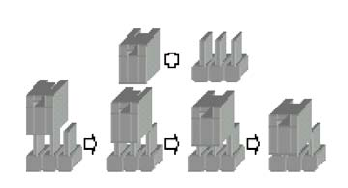
Figure 3 Jumper Connector
For a three-pin jumper (see Figure 3), the jumper setting is designated “1-2” when
the jumper connects pins 1 and 2. The jumper setting is designated “2-3” when pins
2 and 3 are connected and so on. You will see that one of the lines surrounding a
jumper pin is thick, which indicates pin No.1.
To move a jumper from one position to another, use needle-nose pliers or tweezers
to pull the pin cap off the pins and move it to the desired position.


