


Chapter 2
21
KEM
X
-
2030
User’s Manua
l
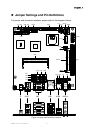
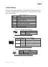
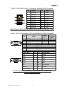
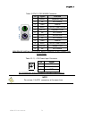
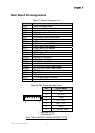
Jumper Settings and Pin Definitions
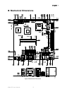
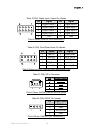
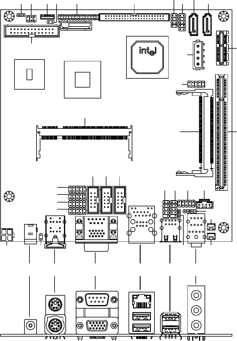
For jumper and connector locations, please refer to the diagrams below.
J1 CN10 CN1 CN9 USB2 AUDIO1
JP4
MPCI 1
CN3
CN11
SATA2
S
A
TA1FP1
FP2IDE1LVDS1CN2
LPT1
JP2JP1 JP3
PCI 1
PCIE 1
COM2
DIMM1
COM3 COM4
USB4 USB3 CN4 CN5
CN6
CN7
CN8
JP9ATX1 JP8
JP5
JP6
JP7
Figure 4 Jumper and Connector Locations