


LE-370 User’s Manual I/O Port Pin Assignment
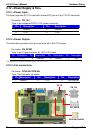
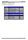
A.2 <Floppy Port>
Connector: FDD
Type: 26-pin connector
Pin Description Pin Description
1 VCC 2 INDEX
3 VCC 4 DRV0
5 VCC 6 DSKCHG
7 DRV1 8 N/C
9 MTR1 10 MTR0
11 RPM 12 DIR
13 N/C 14 STEP
15 Ground 16 WRITE DATA
17 Ground 18 WRITE GATE
19 N/C 20 TRACK 0
21 N/C 22 WRPTR
23 Ground 24 RDATA-
25 Ground 26 SEL
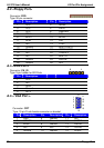
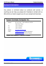
A.3 <IrDA Port>
5 1
Connector: CN_IR
Type: 5-pin header for SIR Ports
Pin Description
1 VCC
2 N/C
3 IRRX
4 Ground
5 IRTX
6
10
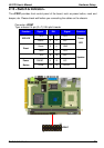
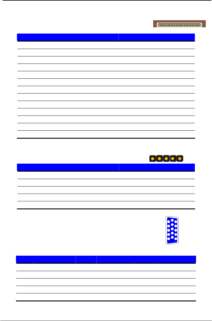
A.4 < VGA Port >
11
12
13
14
15
1
2
3
4
5
Connector: CRT
Type: 15-pin D-sub female connector on bracket
Pin Description Pin Description Pin Description
1 RED 6 Ground 11 N/C
2 GREEN 7 Ground 12 5VSDA
3 BLUE 8 Ground 13 HSYNC
4 N/C 9 N/C 14 VSYNC
5 Ground 10 Ground 15 5VSCL
Floppy Port
38