


INSTALLATIONS
MB900-R User’s Manual 11
[
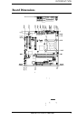
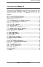
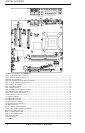
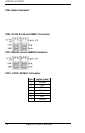
Connectors on MB900 -R
The connectors on MB900 -R allows you to connect external devices such
as keyboard, floppy disk drives, hard disk drives, printers, etc. The
following table lists the connectors o n MB900-R and their respective
functions.
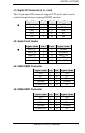
ATX1: 24-pin ATX Power Connector ................................ .................13
ATX2: ATX 12V Power Connector ................................ ..................... 13
MB900-R Edge Connectors ................................ ................................ .13
CN1: PS/2 Keyboard and PS/2 Mouse Connectors .............................. 14
CN2, J2, J7, J8: COM1/2/3/4 Serial Ports ................................ ............14
CN3: Parallel Port Connector ................................ ............................... 15
CN4: VGA CRT Connector ................................ ................................ .15
CN5: Audio Connector ................................ ................................ .........16
CN6: 10/100 RJ-45 and USB0/1 Connector ................................ .........16
CN7: GbE RJ-45 and USB2/3 Connector ................................ ............16
CN11, CN10: SATA0/1 Connector ................................ ...................... 16
J1: Digital I/O Connector (4 in, 4 out) ................................ ..................17
J3: Audio Front Header ................................ ................................ ........17
J5: USB4/USB5 Connector ................................ ................................ ..17
J6: USB6/USB7 Connector ................................ ................................ ..17
J9: Wake On LAN Connecto r ................................ .............................. 18
J10: System Function Connector ................................ .......................... 18
J11: IrDA Connector ................................ ................................ ............18
FAN1: CPU Fan Power Connector ................................ ...................... 18
FAN2, FAN3, FAN4: Fan Power Connectors ................................ ......19
IDE1: Primary IDE Connectors ................................ ............................ 19
PCIE_1: x16 PCI Express Slot ................................ ............................. 19
PCIE_2: x1 PCI Express Slot ................................ ............................... 19
PCI1, PCI5: PCI Slots ................................ ................................ ..........19
CN12: CF Socket................................ ................................ ..................19
J12: SMBus ................................ ................................ .......................... 19