INSTALLATIONS
18 MB900-R User’s Manual
J9: Wake On LAN Connector
J9 is a 3-pin header for the Wake On LAN function on the motherboard.
The following table shows the pin out assignments of this connector.
Wake On LAN will function properly only with an ATX power supply
with 5VSB that has 1A.
Pin #
Signal Name
1
+5VSB
2
Ground
3
LAN Wakeup
J10: System Function Connector
J10 provides connectors for system indicators that provide light
indication of the computer activities and switc hes to change the computer
status.
Signal Name
Pin #
Pin #
Signal Name
HD_LED+
1
2
PWR/ SLP_LED+
HD_LED-
3
4
PWR/ SLP_LED-
RST_SW-
5
6
PWR_SW+
RST_SW+
7
8
PWR_SW-
Reserved
9
10
NC
J11: IrDA Connector
Pin #
Signal Name
1
+5V
2
No connect
3
Ir RX
4
Ground
5
Ir TX
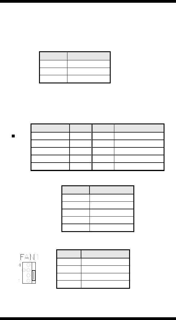
FAN1: CPU Fan Power Connector
Pin #
Signal Name
1
Ground
2
+12V
3
Sense
4
Control


