


13 Intel® RAID Controller SASMF8I Hardware Guide
3Intel
®
RAID Controller SASMF8I
Characteristics
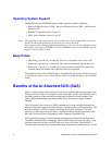
This chapter describes the characteristics of the Intel
®
RAID Controller SASMF8I.
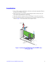
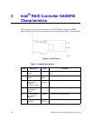
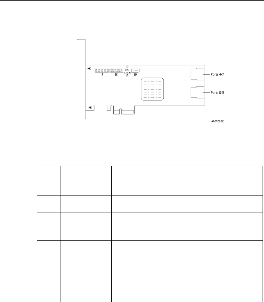
Figure 4 displays the connectors and headers on the controller and Table 1 describes them.
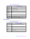
Figure 4. Card Layout
s
Table 1. Jumper Descriptions
Jumper Description Type Comments
J1 Drive Fault LED
header
8x2 header LED signal support for front panel drive fault per
port.
J2 Port activity LED
header
8 x 2
header
LED signal for activity per port.
J4 Universal
Asynchronous
Receiver/
Transmitter (UART)
4-pin
connector
For factory and debug use
J6 Internal SAS/SATA
port connector,
ports 4-7
SFF8087 Connection to SAS/SATA devices.
J7 Internal SAS/SATA
port connector,
ports 0-3
SFF8087 Connection to SAS/SATA devices.
J9 Keyed I
2
C
connector
3-pin
connector
Out-of-band enclosure management (SES2)