


Intel® RAID Controller SRCSATAWB Hardware User’s Guide 10
3 Intel
®
RAID Controller SRCSATAWB
Characteristics
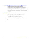
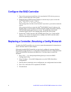
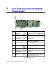
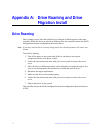
Figure 4. Card Layouts
Jumper Description Type Comments
J1 Dirty cache LED
header
2-pin
header
Provides signal to indicate cache needs to write
data.
J2 On-board BIOS
enable
2-pin
jumper
Default is for no jumper
J3 Serial UART port 4-pin
header
Debug use only
J5 Drive fault LEDs 8x2 header LED signal for drive fault per port for eight ports
(not available through expander)
J6 I
2
C header (SES2) 3-pin
header
Enclosure management support (usually a non-
expander hot-swap backplane)
J7 Battery connector Daughter
card
connector
Connector used for optional battery backup pack
J8 Internal SAS/SATA
port connector
SFF8087 For ports 0 - 3
J9 Internal SAS/SATA
port connector
SFF8087 For ports 4 - 7
J10 Firmware recovery
jumper
2-pin
jumper
This jumper needed only for flashes if the firmware
is corrupted. The card does not function as a
controller if this jumper is in place.
AF002341
J7 J1 J2 J3
J10
J6
J5
J8,
ports 3 - 0
J9,
ports 7 - 4
Speaker
Embedded RAM
LSI* 1078 ROC
Battery Mount Points