


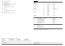
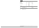

The following abbreviations are used to represent values for Control Module Pin-Out data
I Input PG Power Ground CAN CAN Network D Serial and Encoded Data
O Output SS Sensor / Signal Supply V SCP SCP Network V Voltage (DC)
B+ Battery Voltage SG Sensor / Signal Ground D2 D2B Network PWM Pulse Width Modulated
CAUTION: The information on this data page is furnished to aid the user in understanding circuit operation. THIS INFORMATION SHOULD BE USED FOR
REFERENCE ONLY.
NOTE: The characteristics listed are approximately those that can be expected at the control module connector pins with all circuit connections made and all
components connected and fitted.
Refer to the front of this book for detailed information and illustrations regarding the location and identification of harnesses, relays, fuses, grounds, control
modules and control module pins.
DATE OF ISSUE: December 2001
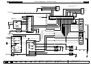
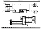
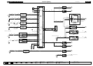
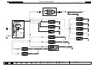
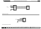
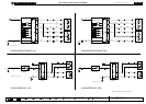
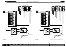
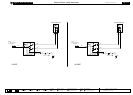
Fig. 10.1
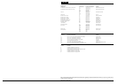
COMPONENTS
Component Connector(s) Connector Description Location
ELECTROCHROMIC REAR VIEW MIRROR RC5 5-WAY / BLACK REAR VIEW MIRROR
INSTRUMENT CLUSTER IP10 26-WAY / YELLOW INSTRUMENT PANEL
IP11 26-WAY / YELLOW
VARIABLE ASSIST SERVO EM91 2-WAY STEERING RACK PINION HOUSING
HARNESS IN-LINE CONNECTORS
Connector Connector Description Location
CA36 16-WAY / GREEN / CABIN HARNESS TO ROOF HARNESS LH LOWER A POST
JB130 22-WAY / GREEN / JUNCTION BOX HARNESS TO INSTRUMENT PANEL HARNESS ADJACENT TO CENTRAL JUNCTION FUSE BOX
JB145 8-WAY / BLACK / ENGINE HARNESS TO JUNCTION BOX HARNESS ADJACENT TO CENTRAL JUNCTION FUSE BOX
GROUNDS
Ground Location
G15 PASSENGER COMPARTMENT / LH LOWER A POST
G36 PASSENGER COMPARTMENT / RH CROSS CAR BEAM
G37 PASSENGER COMPARTMENT / LH CROSS CAR BEAM
FOR CONTROL MODULE PIN-OUT INFORMATION, UNFOLD PAGE TO LEFT.
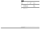
CONTROL MODULE PIN-OUT INFORMATION
Instrument Cluster
Pin Description and Characteristic
C IP10-17 CAN +
C IP10-18 CAN –
I IP11-8 POWER GROUND: GROUND
I IP11-23 VARIABLE ASSIST POWER STEERING FEEDBACK: CLOSED LOOP
I IP11-24 IGNITION SWITCHED POWER SUPPLY: B+
O IP11-25 VARIABLE ASSIST POWER STEERING DRIVE: 864 mA = MAXIMUM ASSIST; 0 mA = MINIMUM ASSIST
NOTE: Refer to the Appendix at the rear of this book for Network Messages.