


12 Configuration Guides—XT-9100 Configuration Guide
An alarm from the High Limit (HIAn) and Low Limit Alarm (LOAn) will
be generated from the unfiltered or filtered input. (See Filter Time
Constant.)
Via the GX Tool
Select XTn, AIn, and Data. At the “Alarm Unfiltered” field, enter “0” for
No (Alarm on Filtered Value), or “1” for Yes (Alarm on Unfiltered
Value).
Via the SX Tool
Select Item AITn.
X6 = 0 Alarm on Filtered Value
X6 = 1 Alarm on Unfiltered Value
Via the GX Tool
(You must first have selected whether the input is active or passive. See
the beginning of Analog Input--Configuration.)
For active inputs, select XTn, AIn, then Data. At the “Type of Active
Input” field, enter:
0 = 0-10 VDC
1 = 4-20 mA
2 = 0-20 mA
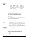
Each analog input module channel performs the conversion of the input
signal to a numeric value using the high range and low range.
Select XTn, AIn, then Data.
High Range = enter the equivalent number for reading at high input
(10V, 20 mA)
Low Range = Enter the reading at low input (0V, 0 mA, 4 mA)
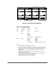
For passive inputs, select XTn, AIn, then Data. At the “Type of Passive
Input” field, enter:
1 = Ni1000 (JCI Type)
2 = Ni1000 Extended Range
3 = A99 (JCI Type)
4 = Pt 1000 (DIN)
Note: Selections 5 and 6 on the screen are not available in the
XT-9100.
For RTD inputs, the range of the displayed value is fixed according to the
type of sensor.
AI Input Type:
Alarm on
Unfiltered Value
AI Input Type:
Input Signal
Range