


14 Configuration Guides—XT-9100 Configuration Guide
Via the SX Tool
The high limit is at Item HIAn (RI.91, RI.99, RI.107, RI.115, RI.123,
RI.131, RI.139, and RI.147), the low limit is at Item LOAn (RI.92,
RI.100, RI.108, RI.116, RI.124, RI.132, RI.140, and RI.148). These Items
may also be set by a Supervisory System and will always be set by
a DX-9100 Controller.
The differential on alarm limits is adjustable with Item ADFn (RI.93,
RI.101, RI.109, RI.117, RI.125, RI.133, RI.141, and RI.149).
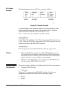
The Filter Time Constant Ts (seconds) is used to filter out any cyclic
instability in the analog input signals. The calculations are:
FV
t
= FV
t-1
+ [1/(1 + T
s
)] * [AI
t
- FV
t-1
]
Where: FV
t
= Filtered Analog Value at current time
FV
t-1
= Filtered Analog Value at previous poll
AI
t
= Actual Analog Value at current time
A value of “0” disables the filter.
Via the GX Tool
Select XTn, AIn, and Data. At the “Filter Constant (sec)” field, enter a
number within the recommended range 0 to 10.
Via the SX Tool
The Filter Time Constant is entered at Item FTCn (RI.94, RI.102, RI.110,
RI.118, RI.126, RI.134, RI.142, and RI.150).
1. When the XT-9100 is connected to a DX-9100 Controller, you can
view the AI value and alarm limits from the DX front panel. See
Display Panel and Keypads in the DX-9100 Extended Digital
Controller Technical Bulletin (LIT-6364020).
2. Analog input values can be read via the SX Tool at Item AIn
(RI.12 to RI.19).
3. Analog input alarm status can be seen via the SX Tool at Item AIS
(RI.11), Bit X1, X3....X15 for high alarm condition and X2, X4....X16
for low alarm condition.
4. Configure all AIs as Active or Passive, whether they are used or
not. A configured AI is shown by a thick bar to the left and right
of its selection box.
Filter Time
Constant
AI Notes