20 Configuration Guides—XT-9100 Configuration Guide
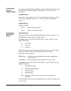
The source of the digital output signal is defined in the DX-9100
Controller.
Via the GX Tool
Select XTn or (EXP), DOn, Data, and then the “Source Point” field. Enter
* and select the required source variable.
Via the SX Tool
Refer to the Extension Module Configuration section in the DX-9100
Configuration Guide (LIT-6364030).
1. When the XT-9100 is connected to a DX-9100 Controller, you can
view and override the DO value from the DX-9100 front panel. See
Display Panel and Keypads in the DX-9100 Extended Digital
Controller Technical Bulletin (LIT-6364020).
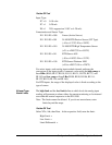
2. The digital output status can be seen at Item DOS1 (DI.07) for XP1
and Item DOS2 (DI.08) for XP2, bits X1-X8 for outputs DO 1-8 with
the SX Tool.
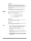
3. A configured DO is shown by a thick bar to the left and right of
its selection box.
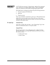
Configure all DOs as ON/OFF or PULSE, whether they are used
or not. The only exception is for the 4-output relay module
(XP-9106). When only one XP-9106 module is installed, select
8DO, but only configure DO1-DO4. When two XP-9106 modules
are installed, configure both as one 8DO module, and configure
DO1-DO8.
DO Source
(with DX-9100
Only)
DO Notes


