


Configuration Guides—XT-9100 Configuration Guide 13
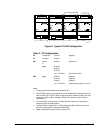
Via the SX Tool
Input Type:
X7 = 0 0-10 volts
X7 = 1 0-20 mA
X8 = 1 20% suppression 2-10V or 4-20 mA)
Linearization and Sensor Type:
X11 X10 X9 = 000 Linear (Active Sensor)
X11 X10 X9 = 001 Ni 1000 RTD Passive Sensor (JCI Type)
(-45 to +121°C/-50 to +250°F)
X11 X10 X9 = 010 Ni 1000 RTD High Temperature Sensor
(+21 to +288°C/70 to +550°F)
X11 X10 X9 = 011 RTD Sensor A99
(-50 to +100°C/-58 to +212°F)
X11 X10 X9 = 100 RTD Sensor Platinum 1000
(+50 to +200°C/-58 to +320°F)
For active inputs, each analog input module channel performs the
conversion of the input signal to a numeric value using the high range at
Item HRn (RI.89, RI.97, RI.105, RI.113, RI.121, RI.129, RI.137, and
RI.145) and low range at Item LRn (RI.90, RI.98, RI.106, RI.114,
RI.122, RI.130, RI.138, and RI.146).
For RTD inputs, the range of the displayed value is fixed according to the
type of sensor.
The high limit and the low limit define at which levels the analog input
reading will generate an alarm, either for remote monitoring or for internal
use within the control sequences in the DX-9100.
Note: The limits cannot be deleted. If you do not want alarms, enter
limits beyond the range.
Via the GX Tool
Select XTn, AIn, then Data. At the respective field, enter the limit:
High Limit =
Low Limit =
Limit Differential =
AI Input Type:
Alarm Limits