


Configuration Guides—XT-9100 Configuration Guide 5
XP9103
DO1
DO2
DO3
DO4
DO5
DO6
DO7
DO8
XP9102
ADDRESS
A B C A B C
RD
TD
Power
RS485
FUSE
HOT GND NEUT
EXP
EXP
FUSE
min
max
XT9100TR9100
EXP
EXP
max
AO7
AO8
min
EXP
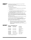
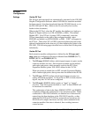
Bus Connector (provided)
emtxt-4
DO5 DO6 DO7 DO8
AI5 AI6 V
AO7
AO8
24VC
24V
COM
24V
COM
DO1 DO2 DO3 DO4
+15V
AI1 AI2 AI3 AI4
XT XP1 XP2TR
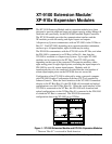
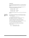
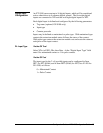
Figure 2: Typical XT-9100 Configuration
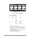
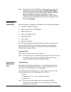
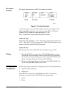
Table 2: XT Configurations
TR
Transformer TR-9100 (optional)
XT
Processor XT-9100
XP1
Analog
or
Digital
XP-9102
XP-9103
XP-9104
XP-9105
1 or 2 x XP-9106
(See Note 1.)
(See Notes 2 and 4.)
XP2
Digital XP-9103
XP-9104
XP-9105
1 or 2 x XP-9106
(optional)
(optional)
(optional)
(optional) (See Notes 2, 3, and 4.)
Notes:
1. The analog XP-9102 must be placed in position XP1.
2. Two XP-9106 modules are considered as one XP module when installed next to each
other in Position XP1 or XP2. When a single XP-9106 is installed in Position XP1 and
another type of XP module is installed in Position XP2, the total number of I/Os is
restricted to 12.
3. The XP-9106 can only be placed in Position XP2 when Position XP1 is filled by an
analog XP or two XP-9106 modules.
4. The first XP-9106 in position XP1 or XP2 controls points DO1-DO4 and the second
XP-9106 in either position controls points DO5-DO8.
5. Digital modules with counters must be in position XP1.