


IDP 75, 250, 800, and 8200 Installation Guide
18 Rack Mounting the IDP Sensor
Rack Mounting the IDP Sensor
The location of the sensor and the layout of your equipment rack or wiring room
are crucial for proper system operation.
Use the following guidelines while configuring your equipment rack.
Enclosed racks must have adequate ventilation. An enclosed rack should have
louvered sides and a fan to provide cooling air.
When mounting a chassis in an open rack, ensure that the rack frame does not
block the intake or exhaust ports. If you install a chassis on slides, check the
position of the chassis when it is seated all the way into the rack.
In an enclosed rack with a ventilation fan in the top, equipment higher in the
rack can draw heat from the lower devices. Always provide adequate
ventilation for equipment at the bottom of the rack.
Baffles can isolate exhaust air from intake air. The best placement of the baffles
depends on the airflow patterns in the rack.
The IDP 75 sensor occupies one rack unit (RU) in an equipment rack. One RU is
1.75 inches (44.45 mm) high. The IDP 250, IDP 800 (copper ports), and IDP 8200
sensors occupy two rack units in an equipment rack.
Required Tools
Rack mounting requires the following tools:
Flathead screwdriver
Number 2 Phillips-head screwdriver
Rack-compatible screws
Rack-mounting brackets (included). Each device comes with the following
brackets:
Two side-mounted rails for mounting to the front and back of the rack
Four midmount brackets for midmounting 2 RU devices
Two midmount brackets for midmounting 1 RU devices
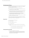
Mounting Using Device Rack Rails
To mount the sensor using the rails in a device rack:
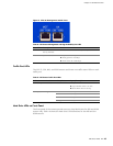
1. Use a flathead screwdriver to attach the rails to each side of the chassis with
the bracket screws. Make sure the hinged brackets are at the back of the
device. Make sure the rails are positioned so they reach the back of the rack
when the device is mounted. See Figure 9.