


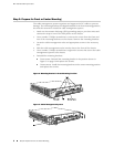
11. Verify that the power cables are not touching or blocking access to router
components, and that they do not drape where people could trip on them.
12. Switch on the external circuit breakers to provide voltage to the DC power source
cable leads.
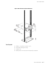
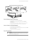
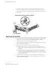
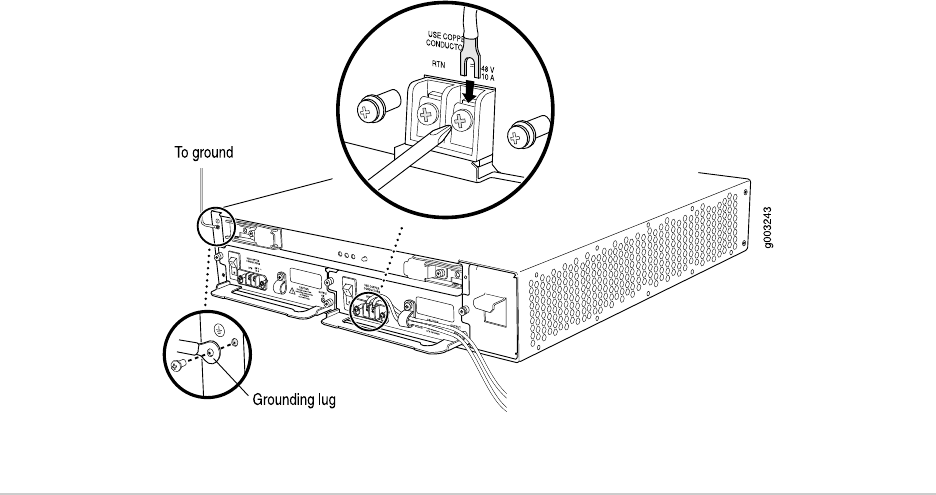
Figure 6: Connect the Power Cables to a DC Router
Step 6: Power On the Router
1. Verify that an external management device is connected to one of the Routing
Engine ports on the Routing Engine (AUX/MODEM, CONSOLE, or MGMT).
2. Turn on the power to the external management device.
3. Verify that the power supply is fully inserted in the chassis and the thumbscrews
on their faceplates are tightened.
4. Verify that the power cord or cables are properly connected:
■ Verify that the ends of the AC power cord are firmly plugged into the
appliance inlet on the power supply faceplate and the external power source
receptacle.
■ Verify that the source DC power cables are connected to the appropriate
terminal on the power supply faceplate: the positive (+) source cable to the
return terminal (labeled RTN) and the negative (–) source cable to the input
terminal (labeled –48V).
5.
Press the power switch on the power supply faceplate to the ON (|) position.
6. Monitor the startup procedure on the external management device to ensure
that the system boots properly.
12 ■ Step 6: Power On the Router
M7i Internet Router Quick Start