


Chapter 3 Configuring the Device
28 User’s Guide
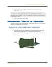
3. Connect the power cables to each NetScreen-ISG 2000 power supply and connect
them to a power source.
4. Connect a 10/100 Base-T cross-over cable from the preferred HA1 port on one
device to the preferred HA1 on the second device.
5. Connect a 10/100 Base-T cross-over cable from the preferred HA2 port on one
device to the preferred HA2 on the second device.
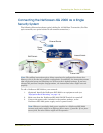
Configuring HA Ports
6. Set the HA interface by executing the following command on each device, for
example:
set interface ethernet4/1 zone ha
set interface ethernet4/2 zone ha
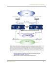
Master Unit
7. If your network is 10/100 Base-T, connect a cross-over cable from ethernet3/8 to
the switch labeled “First Switch 1” in the previous diagram.
8. If your network is fiber optic, connect an optical cable from ethernet2/2 to the
switch labeled “Second Switch 1” in the previous diagram.
9. If your network is fiber optic, connect an optical cable from ethernet1/1 to the
switch labeled “Third Switch 1” in the previous diagram.
Backup Unit
10. If your network is 10/100 Base-T, connect a cross-over cable from ethernet3/8 to
the switch labeled “First Switch 2” in the previous diagram.
11. If your network is fiber optic, connect an optical cable from ethernet2/2 to the
the switch labeled “Second Switch 2” in the previous diagram.
12. If your network is fiber optic, connect an optical cable from ethernet1/1 to the
switch labeled “Third Switch 2” in the previous diagram.
Switches
13. Cable together the “First” switches (which are connected to the
ethernet3/8 ports).
14. Cable together the “Second” switches (which are connected to the
ethernet2/2 ports).
15. Cable together the “Third” switches (which are connected to the
ethernet1/1 ports).
Note: Whenever you deploy both power supplies in a NetScreen-ISG 2000,
connect each power supply to a different power source, if possible. If one power
source fails, the other source might still be operational.