


ENGLISH
9
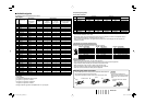
7 Available signals
The following signals are available for this monitor.
Video signals
No. Signal name
Signal format
shown in the
status display
(☞ page 7)
Input terminal
VIDEO
COMPONENT
(Analog
component)
E. AUDIO HD/
SD SDI
(IN 1, IN 2)*
1
DVI-D (HDCP)
(Digital component/
digital RGB)
1 NTSC NTSC
√
—— —
2PAL PAL
√
—— —
3 B/W50 B/W50
√
—— —
4 B/W60 B/W60
√
—— —
5 480/59.94i 480/60i —
√√
—
6 576/50i 576/50i —
√√
—
7 480/59.94p 480/60p —
√
—
√
8 576/50p 576/50p —
√
—
√
9 640∗480/59.94p 640∗480/60p — — —
√
10 720/60p 720/60p —
√√ √
11 720/59.94p 720/60p —
√√ √
12 720/50p 720/50p —
√√ √
13 720/30p 720/30p —
√√
—
14 720/29.97p 720/30p —
√√
—
15 720/25p 720/25p —
√√
—
16 720/24p 720/24p —
√√
—
17 720/23.98p 720/24p —
√√
—
18 1080/60i 1080/60i —
√√ √
19 1080/59.94i 1080/60i —
√√ √
20 1035/60i 1035/60i — √*
2
√
√*
2
21 1035/59.94i 1035/60i — √*
3
√
√*
3
22 1080/50i 1080/50i —
√√ √
23 1080/60p 1080/60p — — —
√
24 1080/59.94p 1080/60p — — —
√
25 1080/50p 1080/50p — — —
√
26 1080/30p 1080/30p —
√√ √
27 1080/29.97p 1080/30p —
√√ √
28 1080/25p 1080/25p —
√√ √
29 1080/24p 1080/24p —
√√ √
30 1080/23.98p 1080/24p —
√√ √
31 1080/30psF 1080/60i — √*
2
√*
2
—
32 1080/25psF 1080/50i — √*
4
√*
4
—
33 1080/29.97psF 1080/60i — √*
3
√*
3
—
34 1080/24psF 1080/24psf —
√√
—
35 1080/23.98psF 1080/24psf —
√√
—
√: Acceptable
—: Not acceptable
*
1
Compatible with EMBEDDED AUDIO signals
*
2
The signal is recognized as 1080/60i.
*
3
The signal is recognized as 1080/59.94i.
*
4
The signal is recognized as 1080/50i.
• Analog component signals are compatible with Y on sync signals.
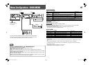
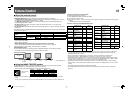
Computer signals (preset)
DVI-D (HDCP) terminals
No. Signal name
Resolution Frequency
Scan system
Horizontal Vertical Horizontal (kHz) Vertical (Hz)
1VGA60 640 480 31.5 59.9 Non-interlace
2WVGA60 852 480 31.5 59.9 Non-interlace
3SVGA60 800 600 37.9 60.3 Non-interlace
4XGA60 1024 768 48.4 60.0 Non-interlace
5WXGA (1280) 1280 768 47.8 60.0 Non-interlace
6WXGA+60 1440 900 55.9 60.0 Non-interlace
7SXGA60*
5
1280 1024 64.0 60.0 Non-interlace
8UXGA60*
5
1600 1200 75.0 60.0 Non-interlace
9 WUXGA60*
5
1920 1200 74.0 60.0 Non-interlace
10 720/60p 1280 720 45.0 59.9/60.0 Non-interlace
11 1080/60p*
5
1920 1080 67.5/67.4 59.9/60.0 Non-interlace
*
5
When signals of No. 7 – 9 and 11 come in, thin lines will become obscured because their signal resolution is higher
than the screen resolution (1440 x 900).
• Non-preset signals may not be displayed normally even if its frequency is within the acceptable range (☞
“Horizontal/vertical frequency (computer signal)” on page 17).
• When a preset signal comes in, the signal format is shown on the status display. For other signals, the
resolution is shown.
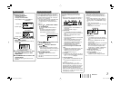
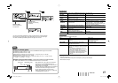
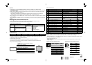
Specification of the DVI-D (HDCP) terminal
Connect it to the DVI-D output terminal on a personal computer.
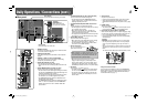
Note for connections
• Before making any connections, turn off all the equipment.
• Use a cord whose plugs correctly match the terminals on this monitor and the equipment.
• Plugs should be firmly inserted; poor connections could cause noise.
• When unplugging a cord, be sure to grasp its plug and pull it out.
• DO NOT connect the power cord until all connections are completed.
• Refer also to the user manual of each piece of equipment.
Pin No. Input signal Pin No. Input signal Pin No. Input signal
1
T.M.D.S Data 2–
9
T.M.D.S Data 1–
17
T.M.D.S Data 0–
2
T.M.D.S Data 2+
10
T.M.D.S Data 1+
18
T.M.D.S Data 0+
3
T.M.D.S Data 2 shield
11
T.M.D.S Data 1 shield
19
T.M.D.S Data 0 shield
4
NC
12
NC
20
NC
5
NC
13
NC
21
NC
6
DDC Clock
14
+5 V Power
22
T.M.D.S Clock shield
7
DDC Data
15
GND
23
T.M.D.S Clock+
8
NC
16
Hot Plug Detect
24
T.M.D.S Clock–
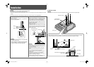
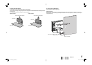
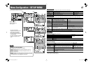
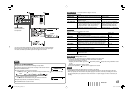
Attaching the power cord holder
• The provided power cord holder prevents accidental disconnection of
the AC power cord from the AC IN terminal.
• The power cord holder consists of two parts, a case and a cover.
CAUTION
• Use only the provided screws.
• Make sure the plug will not be pulled
out after the cover is attached to the
case.
AC IN terminal
Cover
21
Case
3
Tab
• To detach the cover, release
the tab.
DT-V17L2D_EA_EN_R.indd 9DT-V17L2D_EA_EN_R.indd 9 07.9.14 7:01:45 PM07.9.14 7:01:45 PM