


14
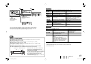
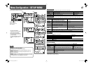
To assign the functions to the pin terminals
For the operation procedure, see page 7.
1 Select “REMOTE SETTING” on the SET-UP MENU.
2 Set “PARALLEL TYPE” to “SET.”
3 Select a pin name (“PIN1” – “PIN5”) for which you want to assign a function, then select the function you want
to assign.
• For selectable functions, see the tables below.
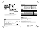
Functions controlled by the MAKE/TRIGGER system
*
5
While controlling with the MAKE system, the screen is switched between normal screen (opening) and blue screen
(short-circuiting). While controlling with the TRIGGER system, the screen changes as same as when pressing
SCREENS CHECK button (☞ page 6).
*
6
Must be controlled with the TRIGGER system. This function cannot be controlled with the MAKE system.
*
7
Selects which functions in “AREA MARKER” are activated, non-“R-” items or “R-” items (☞ page 10).
*
8
While controlling with the MAKE system, the level meter is switched between displayed (short-circuiting) and hidden
(opening). When “LEVEL METER ch” is set to “OFF,” the level meter is not displayed (“NO EFFECT” appears). While
controlling with the TRIGGER system, the pattern of the audio channel display is switched.
*
9
Displays the information shown when INPUT SELECT button of the current input is pressed (☞ “About the Status
Display” on page 7). While controlling with the MAKE system, the information is displayed only at the moment of short-
circuiting.
• You cannot assign the same function to different pin terminals.
• The TRIGGER system switches each function by short-circuiting the pin terminal for about 1 second and
opening it.
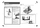
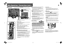
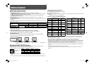
External Control
7 About the external control
This monitor has three external control terminals.
• MAKE/TRIGGER terminal (RJ-45): The following external control systems are available.
(1) MAKE (make contact) system: Controls the monitor by short-circuiting the corresponding pin terminal to
the GND pin terminal, or disconnecting (opening) it (☞ below).
(2) TRIGGER (trigger) system: Controls the monitor by sending the pulse signal instantaneously to the
corresponding pin terminal (☞ below).
• RS-232C terminal (D-sub 9-pin): Controls the monitor with the RS-232C system. (☞ “Using the serial
communication” on page 15)
• RS-485 terminals (RJ-45): Controls the monitor with the RS-485 system. (☞ “Using the serial communication”
on page 15)
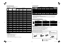
Set the following items of “REMOTE SETTING” in SET-UP MENU according to the external control terminal and
control system (☞ page 13).
Control terminal Control system “SERIAL TYPE” setting “PARALLEL TYPE” setting
MAKE/TRIGGER
terminal
MAKE
—MAKE
TRIGGER
— TRIGGER
RS-485 terminal Serial
communication
RS-485
RS485*
1
—
RS-232C terminal RS-232C
RS232C*
1
—
*
1
On the monitor connected to the personal computer etc, select the terminal the equipment is actually connected to. On
other monitors, select “RS485.”
• Control priority is as follows.
MAKE > TRIGGER, serial communication, and buttons and menu on the monitor
• You can use the external control even when “CONTROL LOCK” is set to “ON” (☞ page 13).
• When the monitor is off (on standby), external control is not available.
<MAKE/TRIGGER system>
You can control the monitor by a personal computer or dedicated controller*
2
. For the details, see below.
*
2
The controller is not commercially available. Consult your dealer if you need it.
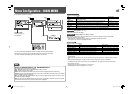
<Serial communication>
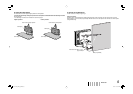
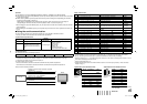
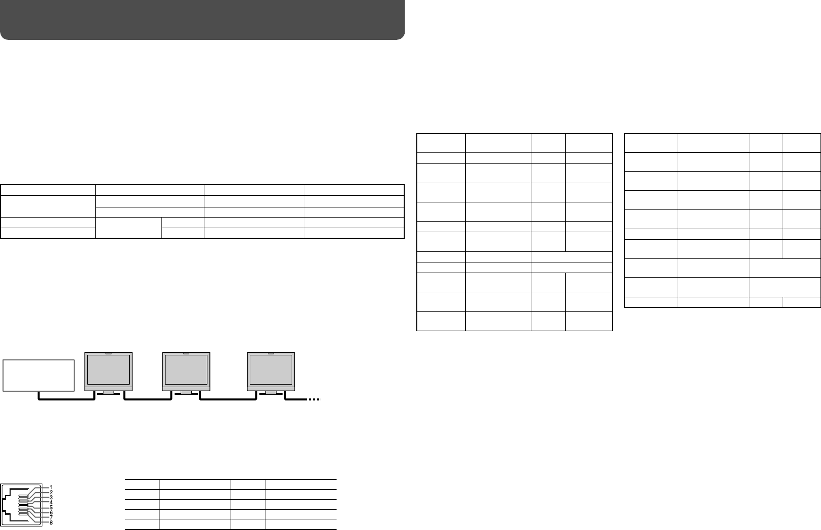
7 Using the MAKE/TRIGGER system
The MAKE/TRIGGER terminal is configured as follows. You can assign a function to each pin terminal in
“REMOTE SETTING” (☞ “PIN1, PIN2, PIN3, PIN4, PIN5” on page 13).
• You cannot change the functions assigned to the pin terminals from 6th to 8th.
PC, etc.
RS-485 IN
or
RS-232C
RS-485
OUT
RS-485
IN
RS-485
OUT
RS-485
IN
RS-485
OUT
Display
Functions to be
controlled
Opening
Short-
circuiting
COMPONENT Changes the input
to “COMPO.”
Invalid Valid
VIDEO Changes the input
to “VIDEO.”
Invalid Valid
TALLY SEL Selects the color of
the tally lamp.
Green Red
SOURCE ID
☞ “SOURCE ID” on
page 13
Off On
MUTING Muting on/off Off On
MARK.SEL Selects the items of
“AREA MARKER”*
7
Non-“R-”
items
”R-” items
L.METER Audio level meter
display
*
8
STATUS Status display*
9
☞ “About the Status
Display” on page 7
— — — No function — —
• See also page 15.
This is a female
terminal.
Pin No. Pin name Pin No. Pin name
1
PIN1
5
PIN5
2
PIN2
6
PIN6 (TALLY)*
3
3
PIN3
7
PIN7 (ENABLE)
*4
4
PIN4
8
PIN8 (GND)
Display
Functions to be
controlled
Opening
Short-
circuiting
COLOR OFF Color off Color Monochrome
ASPECT Changes the
aspect ratio.
4:3 16:9
A.MARKER The area marker
display
Off On
S.MARKER The safety marker
display
Off On
TIME CODE Time code display Off On
1:1 Displays in 1:1
mode.
Off On
SCR CHECK Screens check *
5
I/P MODE I/P MODE *
6
SDI 1 Changes the input
to “SDI 1.”
Invalid Valid
SDI 2 Changes the input
to “SDI 2.”
Invalid Valid
DVI Changes the input
to “DVI.”
Invalid Valid
*
3
The 6th pin terminal controls turning on or off the tally lamp (available to control even when the 7th pin terminal is
invalid).
*
4
The 7th pin terminal makes the external control valid/invalid. Make sure to control the terminal by the MAKE system.
DT-V17L2D_EA_EN_R.indd 14DT-V17L2D_EA_EN_R.indd 14 07.9.14 7:01:49 PM07.9.14 7:01:49 PM