


15
ENGLISH
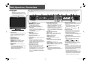
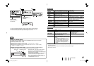
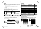
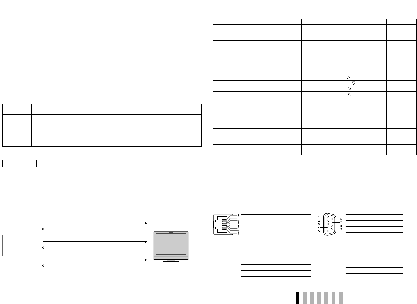
1 Starting the communication: connection command
(!00BCN1Cr)
3 Selecting “SDI 1” input (!00BINACr)
5 Te rminating the communication: termination command
(!00BCN0Cr)
6 Monitor’s status (@00BOKCr)
4 Monitor’s status (@00BOKCr)
2 Monitor’s status (@00BOKCr)
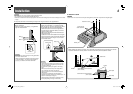
PC, etc.
Monitor
This is a female
terminal.
Pin No. IN terminal
signal
OUT
terminal
signal
1
TXD + TXD +
2
TXD – TXD –
3
RXD + RXD +
4
NC NC
5
NC NC
6
RXD – RXD –
7
NC NC
8
GND GND
This is a female
terminal.
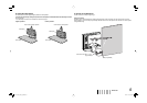
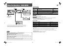
<Specifications of the RS-232C terminal>
Pin No. Signal
1
NC
2
RXD
3
TXD
4
NC
5
GND
6
NC
7
RTS
8
CTS
9
NC
• The 7th terminal and the 8th terminal
are connected.
<Specifications of the RS-485 terminal>
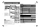
Operation
1 Set “PARALLEL TYPE” of “REMOTE SETTING” to “MAKE” or “TRIGGER” in the SET-UP MENU.
2 Short-circuit the 7th pin terminal (ENABLE) to the 8th pin terminal (GND) so that the monitor can be controlled
by the external control.
3 When selecting “MAKE” system: Operate each function by short-circuiting the corresponding pin terminal to
the 8th pin terminal (GND) or opening it.
When selecting “TRIGGER” system: Operate each function by pulse control, that is short-circuiting the
corresponding pin terminal to the 8th pin terminal (GND) for about 1 second and opening it.
• When changing the input with MAKE system, only one pin terminal must be short-circuited. (Other pin terminals
must be opened.)
• When selecting the “TRIGGER” system, you can operate only one function at a time. Operate the functions one
by one.
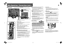
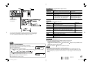
7 Using the serial communication
You can control the monitor from a personal computer etc. via the RS-485 or RS-232C terminal.
• Consult your dealer for the details of the external control specification.
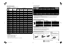
<Communication specifications>
Input terminal Cable
Terminal
specification
Communication specifications
RS-485 A straight LAN cable
☞ See the right
Baud Rate: 4800 bps
Data Bits: 8 bits
Parity: No parity
Stop Bits: 1 bit
Flow Control: No control
Communication Code: ASCII Code
RS-232C A straight cable with a D-sub 9-pin
connector (male for the monitor,
female for the personal computer
etc.)
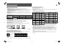
<Command outline>
All commands consist of the following segments.
Header Monitor ID Command ID Function Data Cr (0DH)
Header
“!”: Operation commands from the personal computer, etc. For details, see <Basic command list> on the right.
“?”: Reference commands from the personal computer, etc.
“@”: Status returns from the monitor
• To start communication, send the connection command from the personal computer etc.
• To terminate the communication, send the termination command from the personal computer etc.
Example of communication procedures
<Basic command list>
No. Commands Functions Data
1!
*
**
1
BCN1Cr Starts communication (connection) No data
2!
*
**
1
BCN0Cr Terminates communication (termination) No data
3!
*
**
1
BI DSET x x*
2
Cr Assigns the control ID 01 – 99
4!
*
**
1
BI DRET Cr Initializes the control ID No data
5!
*
**
1
BI DDSP x x*
2
Cr Displays/hides the ID
00: Hide
01: Display
6!
*
**
1
BI DCHK x x*
2
Cr Flashes/hides the selected ID No. of the monitor
00: Hide
01: Display
7!
*
**
1
BMENUCr
Displays the MAIN MENU/Quits the menu
operation
No data
8!
*
**
1
BUPCr
Moves the cursor upward ( )
No data
9!
*
**
1
BDOWNCr
Moves the cursor downward ( )
No data
10 !
*
**
1
BADJ RCrMakes setting/adjustment ( ) No data
11 !
*
**
1
BADJ LCrMakes setting/adjustment ( ) No data
12 !
*
**
1
BSETUP Cr Displays the SET-UP MENU No data
13 !
*
**
1
BPW1 Cr Turns on the monitor No data
14 !
*
**
1
BPW0 Cr Turns off the monitor (on standby) No data
15 !
*
**
1
BI NACr Selects “SDI 1” input No data
16 !
*
**
1
BI NBCr Selects “SDI 2” input No data
17 !
*
**
1
BI NCCrSelects “DVI” input No data
18 !
*
**
1
BI NDCr Selects “COMPO.” input No data
19 !
*
**
1
BI NECr Selects “VIDEO” input No data
20 !
*
**
1
BDISPCrDisplays the status*
3
No data
21 !
*
**
1
BAMUTE x x*
2
Cr Turns muting on/off 00: Off, 01: On
22 !
*
**
1
BASPxx*
2
Cr Changes the aspect ratio 00: 4:3, 01: 16:9
• “Cr” is 0Dh.
• The commands for starting communication (connection) (No. 1), terminating communication (termination)
(No. 2), and turning on the monitor (No. 13) can be used while the monitor is off (on standby).
*
1
Enter the monitor’s ID for “ **.” The initial setting of the monitor’s ID is “00.” When connecting several monitors, “00” is a
command for controlling all monitors at once.
*
2
Enter the appropriate data to “xx”.
*
3
Displays the information shown when INPUT SELECT button of the current input is pressed (☞ “About the Status
Display” on page 7).
DT-V17L2D_EA_EN_R.indd 15DT-V17L2D_EA_EN_R.indd 15 07.9.14 7:01:50 PM07.9.14 7:01:50 PM