


11
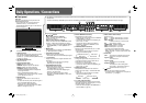
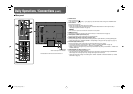
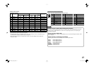
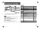
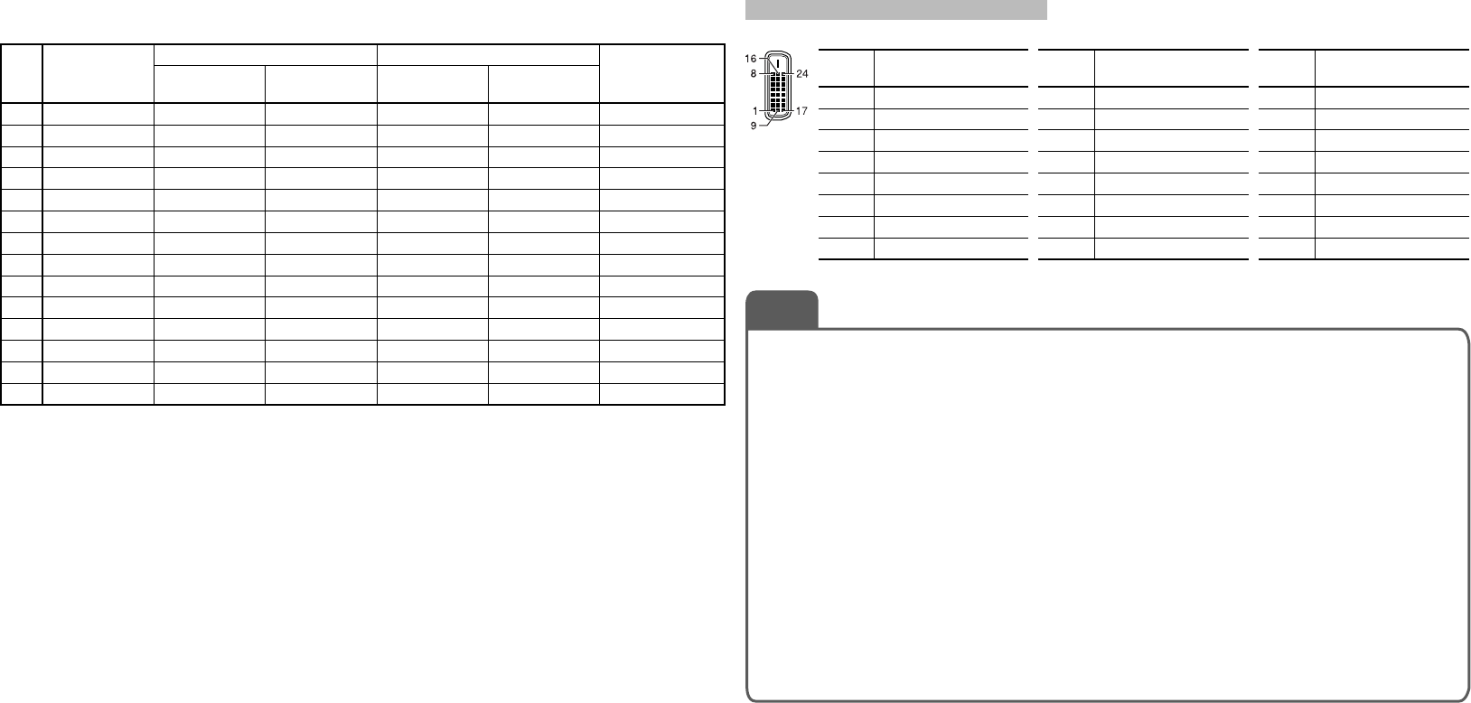
Specification of the DVI-D (HDCP) terminal
Connect it to the DVI-D output terminal on a personal computer.
Pin
No.
Input signal
Pin
No.
Input signal
Pin
No.
Input signal
1
T.M.D.S Data 2–
9
T.M.D.S Data 1–
17
T.M.D.S Data 0–
2
T.M.D.S Data 2+
10
T.M.D.S Data 1+
18
T.M.D.S Data 0+
3
T.M.D.S Data 2 shield
11
T.M.D.S Data 1 shield
19
T.M.D.S Data 0 shield
4
NC
12
NC
20
NC
5
NC
13
NC
21
NC
6
DDC Clock
14
+5 V Power
22
T.M.D.S Clock shield
7
DDC Data
15
GND
23
T.M.D.S Clock+
8
NC
16
Hot Plug Detect
24
T.M.D.S Clock–
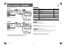
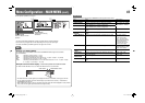
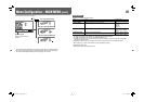
Status indication of DUAL LINK/3G SDI signal information
When DUAL LINK and 3G SDI signals come in, the status of DUAL LINK is displayed. When “SDI DUAL
LINK” (☞ page 12) in MAIN MENU is set to “OFF” and a 3G SDI signal comes in, the 3G SDI signal
information is displayed.
Status indication of DUAL LINK
When “SDI DUAL LINK” (☞ page 12) in MAIN MENU is set to “ON” and an SDI signal is selected, “DUAL
LINK” is displayed.
Status indication of 3G SDI signal information
Following signal information can be displayed when a 3G SDI signal comes in.
3G A-1: Level A mapping structure 1
3G A-2: Level A mapping structure 2
3G A-3: Level A mapping structure 3
3G A-4: Level A mapping structure 4
3G B-DS1: Level B data stream 1
3G B-DS2: Level B data stream 2
3G B-DUAL: Level B DUAL LINK
NOTE
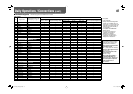
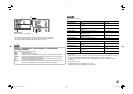
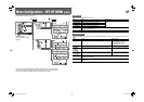
Computer signals (preset)
DVI-D (HDCP) terminals
No. Signal name
Resolution Frequency
Scan system
Horizontal Vertical
Horizontal
(kHz)
Vertical (Hz)
1 VGA60 640 480 31.5 59.9 Non-interlace
2 WVGA60 852 480 31.5 59.9 Non-interlace
3 SVGA60 800 600 37.9 60.3 Non-interlace
4 XGA60 1024 768 48.4 60.0 Non-interlace
5 WXGA (1280) 1280 768 47.8 60.0 Non-interlace
6 WXGA+60
1440 900 55.9
60.0 Non-interlace
7 SXGA60 1280 1024 64.0 60.0 Non-interlace
8 WSXGA+60 1680 1050 65.2 60.0 Non-interlace
9 UXGA60*
5
1600 1200 75.0 60.0 Non-interlace
10 WUXGA60*
5
1920 1200 74.0 60.0 Non-interlace
11 720/60p 1280 720 45.0 60.0 Non-interlace
12 1080/60p*
5
1920 1080 67.5 60.0 Non-interlace
13 720/50p 1280 720 37.5 50.0 Non-interlace
14 1080/50p*
5
1920 1080 56.25 50.0 Non-interlace
*
5
For DT-V20L3GZ: When No. 9, 10, 12 or 14 signals come in, thin lines will become obscured because their
signal resolution is higher than the screen resolution.
• Non-preset signals may not be displayed normally even if their frequency is within the acceptable range (☞
“Horizontal/vertical frequency (computer signal)” on page 26).
• When a preset signal comes in, the signal format is shown on the status display. For other signals, the
resolution is shown.
DT-V24G1_20L3G_US.indd 11DT-V24G1_20L3G_US.indd 11 11.1.20 4:49:51 PM11.1.20 4:49:51 PM