


8
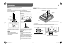
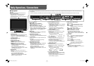
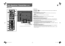
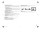
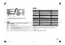
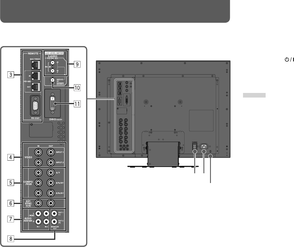
7 Rear panel
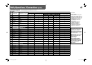
Daily Operations / Connections (cont.)
8
1 POWER switch
Turns AC power on or off.
• You need to press
button (☞ u on page 6) to use the monitor after turning on the POWER switch.
2 AC IN terminal
AC power input connector.
Connect the provided AC power cord to an AC outlet.
• Attach the provided power cord holder to prevent accidental disconnection of the AC power cord (☞
“Attaching the power cord holder” on page 9).
CAUTION
Do not connect the power cord until all other connections are completed.
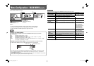
3 REMOTE terminal
Terminal for controlling the monitor by an external control (☞ “External Control” on page 21).
4 VIDEO (INPUT 1/INPUT 2) terminals (BNC)
Input (IN) and output (OUT) terminals for the composite signals.
5 COMPO./RGB (G/Y, B/PB/B-Y, R/PR/R-Y) terminals (BNC)
Input (IN) and output (OUT) terminals for the analog component (color difference) or analog RGB signals.
• Select the signal type in “COMPO./RGB SEL.” corresponding to the type of the input signal (☞ page 12).
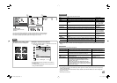
6 EXT.SYNC (CS) terminals (BNC)
Input (IN) and output (OUT) terminals for the external composite sync (Cs) signals.
• To use these terminals, set “SYNC INPUT SEL.” to “EXT.” (☞ “SYNC FUNCTION” on page 15).
• The terminals are for all VIDEO (INPUT 1, INPUT 2) and COMPO./RGB.
• When an external sync signal is input, external synchronization has priority over all VIDEO 1, VIDEO 2 and
COMPO./RGB input.
7 AUDIO ASSIGN (IN 1/IN 2) terminals (pin jack)
Input terminals for the analog audio signals.
• Use this terminal for the analog audio connection of the SDI. When a superimposed signal (EMBEDDED
AUDIO signal on an SDI signal) is input, analog audio signals cannot be input.
• Select the video input to assign the audio signal in “AUDIO1 ASSIGN.” or “AUDIO2 ASSIGN.” (☞ “AUDIO
SETTING” on page 14).
21
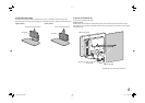
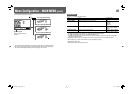
Security slot
Attach a security wire to this slot.
The illustration of the monitor is of DT-V24G11Z.
DT-V24G1_20L3G_US.indd 8DT-V24G1_20L3G_US.indd 8 11.1.20 4:49:48 PM11.1.20 4:49:48 PM