


ENGLISH
13
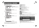
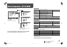
To assign the functions to the pin terminals
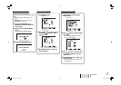
For the operation procedure, see page 7.
1 Select “REMOTE SETTING” on the SET UP MENU.
2 Select a pin name (“PORT F1” – “PORT F6”) for which you want to assign a function, then select
the function you want to assign.
• For selectable functions, see the tables below.
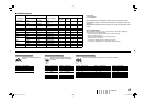
Display Functions to be controlled Opening Short-circuiting
VIDEO 1
Changes the input to “VIDEO 1.” Invalid Valid
VIDEO 2
Changes the input to “VIDEO 2.” Invalid Valid
RGB
Changes the input to “RGB.” Invalid Valid
DVI
Changes the input to “DVI.” Invalid Valid
STD.
Changes the Picture Mode to “STD.” Invalid Valid
DARK
ENHANCED
Changes the Picture Mode to “DARK
ENHANCED.”
Invalid Valid
VIVID
Changes the Picture Mode to “VIVID.” Invalid Valid
DYNAMIC
Changes the Picture Mode to “DYNAMIC.” Invalid Valid
AUTO ADJ.
Adjusts the size/position of the picture. Invalid Valid
SCAN SIZE
Selects the screen size. OVER NARROW
ASPECT
Changes the aspect ratio. 4:3 16:9
STAND BY/ON
*2
Tur ns on/off (on standby) the power.
☞ page 6 “p button”
– – –
No function – –
*
• You cannot assign the same function to different pin terminals.
• The TRIGGER system switches each function by short-circuiting the pin terminal for about 1
second and opening it.
*
2
Must be controlled with the TRIGGER system.
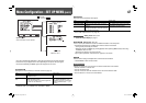
Operation
1 Select the control method (“SYSTEM”) in “REMOTE SETTING.”
2 Short-circuit the 7th pin terminal (ENABLE) to the 8th pin terminal (GND) so that the monitor can
be controlled by the external control.
3 When selecting “MAKE”: Operate each function by short-circuiting the corresponding pin
terminal to the 8th pin terminal (GND) or opening it.
When selecting “TRIGGER”: Operate each function by pulse control, that is short-circuiting the
corresponding pin terminal to the 8th pin terminal (GND) for about 1 second and opening it.
• When changing the input or Picture Mode with the MAKE system, only one pin terminal must be
short-circuited. (Other pin terminals must be opened.)
• When selecting the TRIGGER system, you can operate only one function at a time. Operate the
functions one by one.
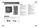
External Control
7 About the external control
This monitor has the MAKE/TRIGGER terminal, which allows you to control the monitor by the make
contact or the trigger system.
• MAKE (make contact) system: Controls the monitor by short-circuiting the corresponding pin
terminal to the GND pin terminal, or disconnecting (opening) it.
• TRIGGER (trigger) system: Controls the monitor by sending the pulse signal instantaneously to
the corresponding pin terminal.
Control priority is as follows.
MAKE > TRIGGER/buttons and menu on the monitor
• You can use the external control even when “CONTROL LOCK” is set to “ON” (☞ page 12).
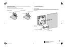
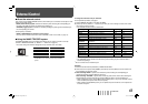
7 Using the MAKE/TRIGGER system
The MAKE/TRIGGER terminal is configured as follows. You can assign a function to each pin
terminal in “REMOTE SETTING” (☞ “PORT F1” – “PORT F6” on page 12).
• You cannot change the functions assigned to the pin terminals from 7th and 8th.
Pin No. Pin name Pin No. Pin name
1
PORT F1
5
PORT F5
2
PORT F2
6
PORT F6
3
PORT F3
7
ENABLE
*1
4
PORT F4
8
GND
*
1
The 7th pin terminal makes the external control valid/
invalid. Make sure to control the terminal by the MAKE
system.
This is a female terminal.
LMH191&171EA_EN.indd 13LMH191&171EA_EN.indd 13 08.7.8 5:40:28 PM08.7.8 5:40:28 PM