


7
ENGLISH
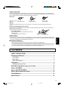
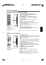
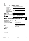
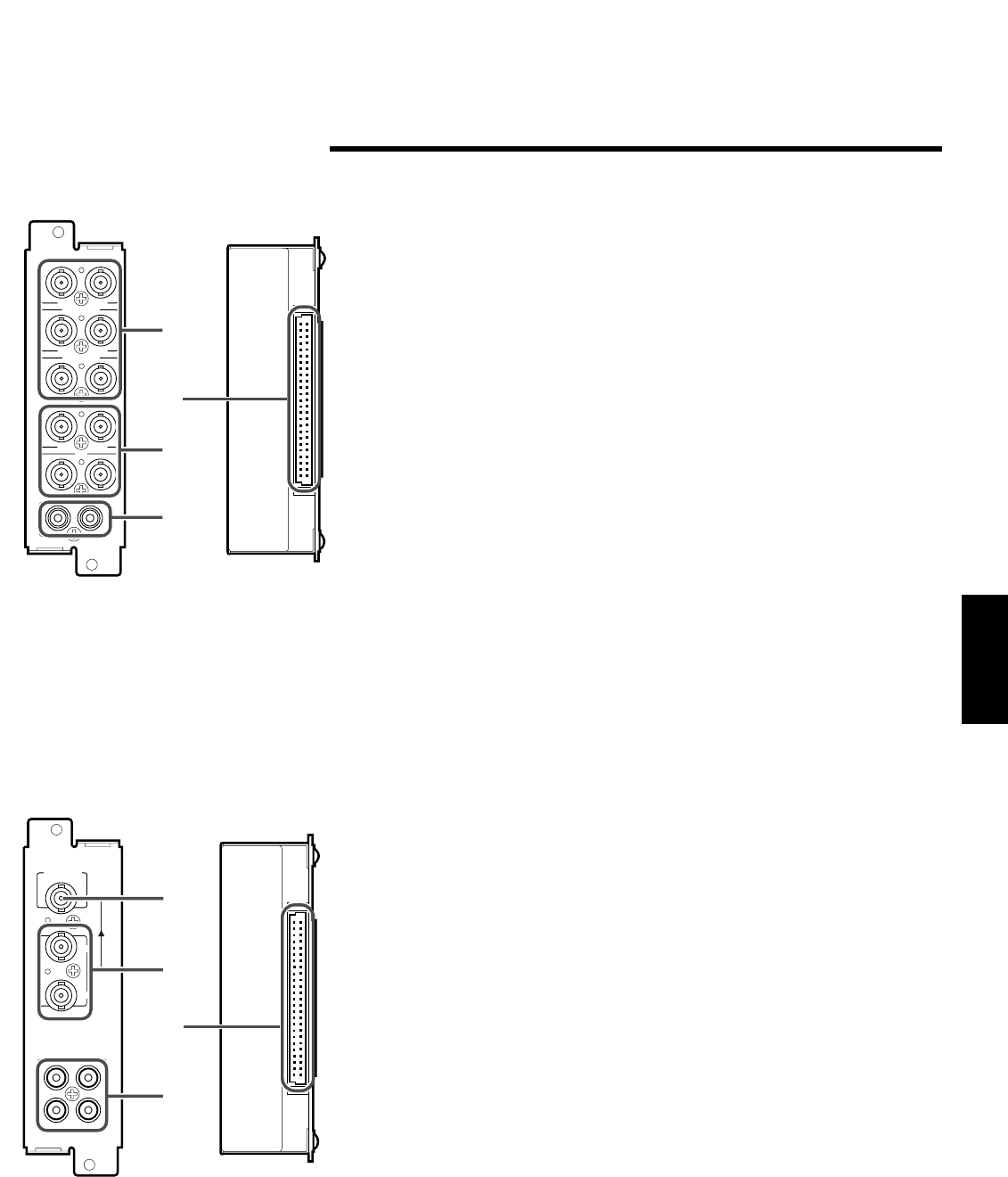
7 Component/RGB Input Card (IF-C01COMG)
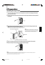
Input Card (option)
7 Acceptable signal formats when installed
on this monitor:
525/60i, 625/50i
• G on SYNC cannot be used with the
RGB input.
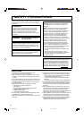
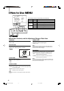
1 SWITCHED OUT terminal
Output (OUT) terminal for the re-clocked signal. The input signal from
the input terminal currently selected (SDI 1 or SDI 2) is re-clocked
and output from this terminal.
NOTES:
• No signal is output from the SWITCHED OUT terminal when the main power is turned
off.
• Even when the input signal is switched from the SDI Input Card, the SWITCHED OUT
terminal still outputs the SDI 1 or SDI 2 re-clocked signal which is selected last time.
The re-clocked signal from SDI 1 is output from the SWITCHED OUT terminal when
the monitor is in stand-by mode.
2 D1 SDI signal input terminal (SDI 1, SDI 2)
Accepts the SMPTE259M D1 SDI signal. The audio signal of the
EMBEDDED AUDIO signal cannot be decoded (only the video signal
can be decoded).
To select SDI 1: Press the INPUT SELECT C button.
To select SDI 2: Press the INPUT SELECT D button.
3 Connection terminal
Attach to the connection terminal of the input card slot on the
monitor.
4 Audio signal input/output terminals (for both SDI 1 and
SDI 2)
Input (IN) and output (OUT) terminals for the analog audio signals.
• The IN and OUT terminals are bridge-connected.
7 SDI Input Card (IF-C01SDG)
7 Acceptable signal formats when installed
on this monitor:
525/60i, 625/50i
B/P
B
/B-Y
G/Y
OUTIN
OUTIN
R/P
R
/R-Y
OUTIN
VD
OUTIN
HD/C
S
OUTIN
OUTIN
AUDIO
OUT
IN
1
2
3
4
AUDIO 2
AUDIO 1
OUT
IN
SWITCHED
OUT
SDI 1
SDI 2
IN
IN
1
2
3
4
1 Component/RGB signal input/output terminals
Input (IN) and output (OUT) terminals for the component (color
difference) or the RGB signal.
To select Component signal: Press the INPUT SELECT C button.
To select RGB signal: Press the INPUT SELECT D button.
• The IN and OUT terminals are bridge-connected (auto termination).
2 Connection terminal
Attach to the connection terminal of the input card slot on the
monitor.
3 Synchronized signal input/output terminals
Input (IN) and output (OUT) terminals for the vertical, horizontal or
complex synchronized signals.
• The IN and OUT terminals are bridge-connected (auto termination).
NOTE:
These terminals are available only to the RGB input.
4 Audio signal input/output terminals
Input (IN) and output (OUT) terminals for the analog audio signals.
• The IN and OUT terminals are bridge-connected.
NOTE:
You cannot connect both the component signal outputs and the RGB signal outputs at a
time.
[04-09]_TM-H150CG.p65 04.1.17, 4:05 PM7