


TM-H1700G
1-3
No.51922
ENGLISH
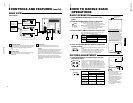
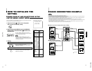
REMOTE (external control) terminal
Connect this terminal to an external control unit to enable
remote operation of the monitor.
Refer to the HOW TO USE EXTERNAL CONTROL on
page 15 for more details.
Video A terminals [VIDEO A IN/OUT]
Video signal input (IN) and output (OUT) terminals.
The output terminal is bridge-connected.
IN : Video signal input terminal
OUT : Bridge-connected video signal output terminal
Notes:
* For corresponding audio signals, use the AUDIO A
terminals
%
.
* Also refer to BASIC CONNECTION EXAMPLE
on page 13.
Video B terminals [VIDEO B IN/OUT]
Video signal input (IN) and output (OUT) terminals.
The output terminal is bridge-connected.
IN : Video signal input terminal
OUT : Bridge-connected video signal output terminal
Notes:
* For corresponding audio signals, use the AUDIO B
terminals
^
.
* Also refer to BASIC CONNECTION EXAMPLE on
page 13.
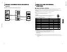
Video B (Y/C) terminals [VIDEO B Y/C IN/OUT]
Y/C (S-video) signal input (IN) and output (OUT) termi-
nals. The output terminal is bridge-connected.
IN :Y/C-separated (S-video) video signal input
terminal
OUT :Bridge-connected Y/C-separated (S-video) signal
output terminal.
REAR VIEW
<Rear Panel>
11
12
13
14
5
Notes:
* For corresponding audio signals, use the AUDIO B
terminals
^
.
* When both VIDEO B terminals are connected (input) at
the same time, the Y/C terminal has priority.
* Also refer to BASIC CONNECTION EXAMPLE
on page 14.
Audio A terminals [AUDIO A IN/OUT]
Input (IN) and output (OUT) terminals for the audio signal
corresponding to the VIDEO A terminals
@
.
The output terminal is bridge-connected.
IN : Audio signal input terminal
OUT : Bridge-connected audio signal output terminal
Notes:
* For corresponding video signals, use the VIDEO A
terminal
@
.
* Also refer to BASIC CONNECTION EXAMPLE
on page 13.
Audio B terminals [AUDIO B IN/OUT]
Input (IN) and output (OUT) terminals for the audio
signals corresponding to the VIDEO B terminals
#
VIDEO B (Y/C)
$
.
The output terminal is bridge-connected.
IN : Audio signal input terminal
OUT : Bridge-connected audio signal output terminal
Notes:
* For corresponding video signals, use the VIDEO B
terminals
#
or VIDEO B (Y/C) terminals
$
.
* Also refer to BASIC CONNECTION EXAMPLE
on pages 13 and 14.
15
12
11
13
14
15
16
VIDEO A
REMOTE
AUDIO A
AUDIO B
VIDEO B
IN OUT
IN
IN
IN
OUT
OUT
IN
OUT
Y/C
OUT
VIDEO A
AUDIO A
AUDIO B
VIDEO B
IN OUT
IN
IN
IN
OUT
OUT
IN
OUT
Y/C
OUT
16
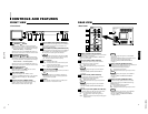
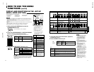
Chroma/Phase button
[
CHROMA/ PHASE]
Press this button to activate the picture color density
adjustment mode or picture hue adjustment mode. Each
time you press the button, the adjustment item changes.
Picture color density
f
Picture hue
Adjust the value with the VOLUME/SELECT buttons
3
.
Also used as a control button in the menu function mode.
Contrast/Brightness button
[CONTRAST
/ BRIGHT ]
Press this button to activate the picture contrast adjust-
ment mode or picture brightness adjustment mode. Each
time you press the button, the adjustment item changes.
Picture contrast
f
Picture brightness
Adjust the value with the VOLUME/SELECT buttons
3
.
Also used as a control button in the menu function mode.
Volume/Select buttons
[VOLUME/SELECT –
+]
Adjusts the speaker volume. Also used as a control
button in the menu function mode.
Menu button [MENU]
Displays and disappears the <MENU> screen.
Pressing the CHROMA/PHASE button
1
with the Menu
button depressed will display the <SET-UP MENU>
screen.
Under Scan button [UNDER SCAN]
Reduces the screen size to display the entire image.
Press the button again to cancel Under Scan.
When selected, the Under Scan button lights.
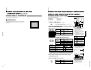
CONTROLS AND FEATURES
FRONT VIEW
<Front Panel>
Input A (VIDEO) button [INPUT SELECT A]
Selects the video and audio signals input to the VIDEO A
@
and AUDIO A
%
terminals on the rear panel. The
button lights when selected.
Input B (VIDEO Y/C) button [INPUT SELECT B]
Selects the video and audio signals input to the VIDEO B
#
or VIDEO B (Y/C)
$
and AUDIO B
^
terminals on
the rear panel. The button lights when selected.
Note:
● The VIDEO B terminals include a video terminal (BNC
connector) and a Y/C terminal (mini-DIN 4-pin connec-
tor). The Y/C (S-video) terminal has priority.
Power indicator
Unlit : The main power is OFF.
Orange : The main power is ON, but the monitor’s power
is OFF (in the stand-by mode).
Green : The main power is ON, and the monitor’s power
is ON (in the normal operation mode).
Power switch [POWER ]
Press the power switch to turn the monitor’s power ON or
OFF when the main power is ON.
Note:
● When RUSH DELAY is set to SLOW, it takes about
three seconds before power is actually supplied after
the power switch is pressed.
Speaker
A built-in speaker is located inside the right side panel
when the monitor is viewed from the front.
1
2
3
4
5
6
7
8
9
10
4
6
8
7
POWER
CHROMA MENU
INPUT SELECT
UNDER
SCAN
PHASE
0C
BRIGHT
CONTRAST VOLUME/SELECT
AB
9
4
5
3
21
10
POWER
CHROMA MENU
INPUT SELECT
UNDER
SCAN
PHASE
TM-H1700G
BRIGHT
CONTRAST VOLUME/SELECT
AB