


TM-H1700G
1-7
No.51922
ENGLISH
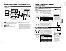
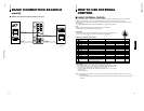
VIDEO A
AUDIO A
AUDIO B
VIDEO B
IN OUT
IN
IN
IN
OUT
OUT
IN
OUT
Y/C
OUT
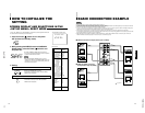
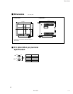
BASIC CONNECTION EXAMPLE
Notes:
•
Before connecting your system, make sure that all units are turned off.
•
The illustration below shows some examples of different connections. Terminal connections may differ depending on the component connected.
Be sure to refer to the instructions provided with the unit(s) you are connecting.
•
Each pair of input (IN) and output (OUT) terminals are bridge-connected.
•
If you’re not connecting any equipment to a bridged output (OUT) terminal, be sure not to connect any other cables to the bridged output (OUT)
terminal as this will cause the terminating resistance switch to open (auto terminate function).
•
When making a bridge connection, connect the input (IN) and output (OUT) terminals on the monitor to separate video components.
(For example, if both terminals are connected to the same VCR, resonance may occur except during playback. This is caused by the same video
signal “looping” between the VCRs, and is not a malfunction.)
•
Select the video input signal (INPUT A(VIDEO) or INPUT B (VIDEO/Y/C)) with the INPUT SELECT buttons on the front panel. When both
VIDEO B terminals are connected (input) at the same time, the Y/C terminal has priority.
Ⅵ VIDEO A Connection Example (Select Input A (VIDEO))
Ⅵ VIDEO B (VIDEO) Connection
Example (Select Input B (VIDEO))
Video Camera
Video Monitor
VCR
Video Camera
Video Monitor
VCR
Video
(Video signal cable)
Audio
(Audio signal cable)
Video
(Video signal cable)
Audio
(Audio signal cable)
Audio
(Audio signal cable)
Video
(Video signal cable)
Video
(Video signal cable)
Video Monitor
VCR
Video Monitor
VCR
: Signal Flow
13
Audio
(Audio signal
cable)
12
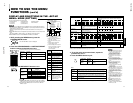
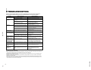
Functions (Items)
Initialization
(setting)
SHARPNESS 00
ADJ. BAR POSI LOWER
COLOR TEMP 6500
COLOR SYSTEM
AUTO
RUSH DELAY STD
ASPECT RATIO 4 – 3
PICTURE SUB ADJ.
CONTRAST 00
BRIGHT 00
CHROMA 00
PHASE 00
H. POSITION 00
V. POSITION 00
WHITE BALANCE
R. CUT OFF 00
G. CUT OFF 00
B. CUT OFF 00
R. DRIVE 00
B. DRIVE 00
CONTROL LOCK OFF
STATUS DISPLAY ON
REMOTE SYSTEM MAKE
INPUT REMOTE A – B
CHROMA 00
PHASE 00
CONTRAST 00
BRIGHT 00
VOLUME 20
<SET–UP MENU> RESET
Are you sure ?
“Yes” then <+>
“No” then <MENU>
Sorts
<MENU> screen
<SET-UP MENU> screen
Volume
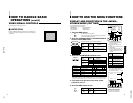
HOW TO INITIALIZE THE
SETTING
SCREEN DISPLAY AND SELECTIONS IN THE
<SET-UP MENU> RESET MODE
You can set <MENU> and <SET-UP MENU> screen items, picture adjustment items and
the volume level to their factory-set (initial) values.
1. Press the Power ( ) switch to turn the power
OFF (activate the standby mode).
The <SET-UP MENU> RESET screen is displayed.
* The screen automatically disappears when no operation
is performed after about 5 minutes.
Initial settings
<SET-UP MENU> RESET screen
2. While pressing both MENU button and CHROMA/
PHASE button, press the Power (
) switch to turn
the power ON.
3. Setting
ⅷ Initialization is required.
ⅷ Initialization is not required.
Press the VOLUME/SELECT [+] button.
* Initialization is completed, and the <SET-UP MENU>
RESET screen disappears.
Press the MENU button.
* Initialization is aborted, and the <SET-UP MENU>
RESET screen disappears.
● The <SET-UP MENU> RESET screen will not be
displayed if the MENU or CHROMA/PHASE buttons are
pressed for a very short time. Keep pressing them until
the display screen appears.
Note:
POWER
MENU
CHROMA
PHASE
POWER
MENU
VOLUME/SELECT
Picture adjustment