


TM-H1750CG
1-3
No.51923
ENGLISH
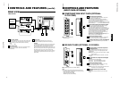
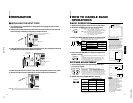
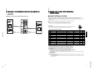
Input card slot (SLOT)
Optional input cards can be installed in this slot. Input
cards are not provided when you purchase this monitor.
REMOTE (external control) terminal
Connect this terminal to an external control unit to enable
remote operation of the monitor.
Refer to the HOW TO USE EXTERNAL CONTROL on
page 17 for more details.
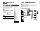
Video A terminals [VIDEO A IN/OUT]
Video signal input (IN) and output (OUT) terminals.
The output terminal is bridge-connected.
IN : Video signal input terminal
OUT : Bridge-connected video signal output terminal
Notes:
*For corresponding audio signals, use the AUDIO A
terminals
q
.
* Also refer to BASIC CONNECTION EXAMPLE
on page 15.
Video B terminals [VIDEO B IN/OUT]
Video signal input (IN) and output (OUT) terminals.
The output terminal is bridge-connected.
IN : Video signal input terminal
OUT :Bridge-connected video signal output terminal
Notes:
*For corresponding audio signals, use the AUDIO B
terminals
w
.
*Also refer to BASIC CONNECTION EXAMPLE on
page 15.
Video B (Y/C) terminals [VIDEO B Y/C IN/OUT]
Y/C (S-video) signal input (IN) and output (OUT) termi-
nals. The output terminal is bridge-connected.
IN :Y/C-separated (S-video) video signal input
terminal
OUT :Bridge-connected Y/C-separated (S-video) signal
output terminal.
REAR VIEW
<Rear Panel>
5
Notes:
* For corresponding audio signals, use the AUDIO B
terminals
w
.
* When both VIDEO B terminals are connected (input) at
the same time, the Y/C terminal has priority.
* Also refer to BASIC CONNECTION EXAMPLE
on page 16.
Audio A terminals [AUDIO A IN/OUT]
Input (IN) and output (OUT) terminals for the audio signal
corresponding to the VIDEO A terminals
*
.
The output terminal is bridge-connected.
IN : Audio signal input terminal
OUT : Bridge-connected audio signal output terminal
Notes:
* For corresponding video signals, use the VIDEO A
terminal
*
.
* Also refer to BASIC CONNECTION EXAMPLE
on pages 15 and 16.
Audio B terminals [AUDIO B IN/OUT]
Input (IN) and output (OUT) terminals for the audio
signals corresponding to the VIDEO B terminals
(
or
VIDEO B (Y/C) terminals
)
.
The output terminal is bridge-connected.
IN : Audio signal input terminal
OUT : Bridge-connected audio signal output terminal
Notes:
* For corresponding video signals, use the VIDEO B
terminals
(
or VIDEO B (Y/C) terminals
)
.
* Also refer to BASIC CONNECTION EXAMPLE
on pages 15 and 16.
18
16
17
19
20
21
22
VIDEO A
REMOTE
SLOT
AUDIO A
AUDIO B
VIDEO B
IN OUT
IN
IN
IN
OUT
OUT
IN
OUT
Y/C
OUT
VIDEO A
AUDIO A
AUDIO B
VIDEO B
IN OUT
IN
IN
IN
OUT
OUT
IN
OUT
Y/C
OUT
16
17
18
19
20
21
22
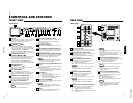
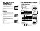
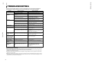
Tally lamp
Lights when the tally control signal is ON. The tally control
signal is input through the REMOTE (external control)
remote terminal. For details, refer to Page 17.
Chroma/Phase button
[
CHROMA/ PHASE]
Press this button to activate the picture color density
adjustment mode or picture hue adjustment mode. Each
time you press the button, the adjustment item changes.
Picture color density
f
Picture hue
Adjust the value with the VOLUME/SELECT buttons
4
.
Also used as a control button in the menu function mode.
Contrast/Brightness button
[CONTRAST / BRIGHT ]
Press this button to activate the picture contrast adjustment
mode or picture brightness adjustment mode. Each time
you press the button, the adjustment item changes.
Picture contrast
f
Picture brightness
Adjust the value with the VOLUME/SELECT buttons
4
.
Also used as a control button in the menu function mode.
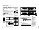
Volume/Select buttons
[VOLUME/SELECT –
+]
Adjusts the speaker volume. Also used as a control
button in the menu function mode.
Menu button [MENU]
Displays and disappears the <MENU> screen.
Pressing the CHROMA/PHASE button
2
with the Menu
button depressed will display the <SET-UP MENU>
screen.
Under Scan button [UNDER SCAN]
Reduces the screen size to display the entire image.
Press the button again to cancel Under Scan.
When selected, the Under Scan button lights.
Color Off button [COLOR OFF]
Cuts color signals to display a black and white image.
Press the button again to restore the original color.
When selected, the COLOR OFF button lights.
Note:
●This function is invalid with RGB input.
CONTROLS AND FEATURES
FRONT VIEW
<Front Panel>
Blue Check button [BLUE CHECK]
Cuts red and green signal components. Only blue signal
components are shown. Press the button again to
restore the normal image.
When selected, this button lights.
Aspect button [ASPECT]
Press this button to change the aspect ratio from 4:3 to
16:9.
Input A (VIDEO) button [INPUT SELECT A]
Selects the video and audio signals input to the VIDEO A
*
and AUDIO A
q
terminals on the rear panel. The
button lights when selected.
Input B (VIDEO Y/C) button [INPUT SELECT B]
Selects the video and audio signals input to the VIDEO B
(
or VIDEO B (Y/C)
)
and AUDIO B
w
terminals on
the rear panel. The button lights when selected.
Note:
●The VIDEO B terminals include a video terminal (BNC
connector) and a Y/C terminal (mini-DIN 4-pin connector).
The Y/C (S-video) terminal has priority.
Input C/D (Slot) buttons [INPUT SELECT C/D
(SLOT)]
Selects the signals to be input via the input cards installed
in the rear panel card slots.
C, D: Selects the image from the input card in the slot.
For details on input connectors and using the INPUT
SELECT button, refer to page 7.
Power indicator
Unlit : The main power is OFF.
Orange : The main power is ON, but the monitor’s power
is OFF (in the stand-by mode).
Green : The main power is ON, and the monitor’s power
is ON (in the normal operation mode).
Power switch [POWER ]
Press the power switch to turn the monitor’s power ON or
OFF when the main power is ON.
Note:
●When RUSH DELAY is set to SLOW, it takes about
three seconds before power is actually supplied after
the power switch is pressed.
Speaker
A built-in speaker is located inside the right side panel
when the monitor is viewed from the front.
1
2
3
4
5
6
7
8
9
10
11
12
13
14
4
15
POWER
CHROMA MENU
ASPECT
INPUT SELECT
SLOT
UNDER
SCAN
COLOR
OFF
BLUE
CHECK
PHASE
TM-H1750CG
BRIGHT
CONTRASTVOLUME/SELECT
AB
CD
1
4
8 9 10 11 12 1413
7
POWER
CHROMA MENU
ASPECT
INPUT SELECT
SLOT
UNDER
SCAN
COLOR
OFF
BLUE
CHECK
PHASE BRIGHT
CONTRAST VOLUME/SELECT
AB
CD
2
3
56
15