


TM-H1750CG
1-4
No.51923
ENGLISH
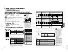
Video input/output terminals
Input (IN) and output (OUT) terminals for component
(color deference) or RGB signals.
The IN and OUT terminals are bridge-connected.
(When no cable is connected to the OUT terminal, the
input signal is automatically terminated.)
Select component signal :press INPUT SELECT C button
Select RGB signal :press INPUT SELECT D button
Synchronized signal input/output terminals
Input (IN) and output (OUT) terminals for the vertical,
horizontal or complex synchronized signals.
The synchronized signals from these terminals have
priority over other terminals. When no synchronized signal
is input to these terminals, the synchronized signal from
the video input/output terminals (G/Y terminals) is valid.
The IN and OUT terminals are bridge-connected.
(When no cable is connected to the OUT terminal, the
input signal is automatically terminated.)
External sync is available with RGB input only. G on
SYNC cannot be used with RGB input.
Audio input/output terminals
Input (IN) and output (OUT) terminals for audio signals.
The IN and OUT terminals are bridge-connected.
Connection terminal (to a Color Video Monitor)
Attach to the connection terminal of your color video
monitor.
1
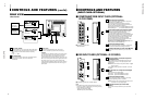
CONTROLS AND FEATURES
(INPUT CARD: OPTIONAL)
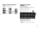
Ⅵ COMPONENT/RGB INPUT CARD (OPTIONAL:
IF-C01COMG)
B/P
B
/B-Y
G/Y
OUTIN
OUTIN
R/P
R
/B-Y
OUTIN
VD
OUTIN
HD/C
S
OUTIN
OUTIN
AUDIO
OUT
IN
1
2
3
4
ⅥCompatible signal formats:
480/50i, 480/60i
2
3
4
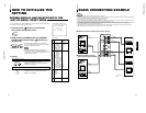
Ⅵ SDI INPUT CARD (OPTIONAL: IF-C01SDG)
AUDIO 2
AUDIO 1
OUT
IN
SWITCHED
OUT
SDI 1
SDI 2
IN
IN
1
2
3
4
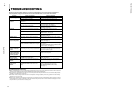
Output terminal for a selected component
serial digital signal
Output terminal for a selected digital signal (the input
displayed on the screen). The output signal is cable-
compensated.
NOTE: When the monitor’s main power is OFF, no digital
signal is output.
In the standby mode, signals from the SDI 1 connector
are output.
Input terminals for component serial digital
signals
Input terminals for the digital signal.
Select SDI 1 : press INPUT SELECT C button
Select SDI 2 : press INPUT SELECT D button
Audio input/output terminals
Input (IN) and output (OUT) terminals for the analog
signals corresponding to SDI 1 and SDI 2.
NOTE: This input card cannot decode audio data even if
contained in the input digital signal.
Connection terminal (to a Color Video
Monitor)
Attach to the connection terminal of your color video
monitor.
1
ⅥCompatible signal formats: 480/60i, 480/50i
Note:
●The optional input cards shown below cannot be used.
Using any of these cards will void your warranty and may
result in damage or malfunction.
*Video input card (IF-C01PNG)
*HD-SDI input card (IF-C01HSDG)
2
3
4
7
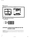
24 23
25
25
25
VIDEO A
REMOTE
SLOT
AUDIO A
AUDIO B
VIDEO B
IN OUT
IN
IN
IN
OUT
OUT
IN
OUT
Y/C
OUT
REAR VIEW
<Rear Panel>
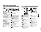
CONTROLS AND FEATURES
(cont’d)
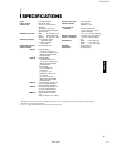
6
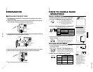
Main power switch
Press the switch to turn the main power ON or OFF. When
the main power is ON, the power lamp on the front panel
lights in orange and the monitor enters the stand-by
mode.
I : ON ⅜ : OFF
AC inlet [AC IN]
Power input connector. Connect the provided AC power
cord
t
to an AC outlet (120 V AC or 230 V AC,
50 Hz/60 Hz).
To AC outlet
(230 V AC,
50 Hz/60 Hz)
For the United Kingdom
For Europe
23
Power cord
Connects the provided power cord (120 V AC or
230 V AC, 50 Hz/60 Hz) to the AC IN connector
r
.
Caution:
In North America (USA and Canada), this monitor comes
with one power cable. In Europe and the United King-
dom, two power cables are provided (one for use in
continental European countries and the other for the UK).
Be sure to use the power cable that is appropriate for the
AC outlets used in your region. If none of the power
cables provided is suitable, please contact your dealer or
qualified service personnel to obtain the correct type of
power cable.
To AC outlet
(120 V AC,
50 Hz/60 Hz)
For U.S.A. and Canada
24
25