


TM-H1750CG
1-5
No.51923
ENGLISH
PAL
VOLUME : 20
PHASE : 00
+
–
INPUT
SELECT
buttons
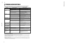
Items
VOLUME/SELECT button
– +
CHROMA
lighter deeper
(Chroma)
PHASE
reddish greenish
(Phase)
CONTRAST
lower higher
(Contrast)
BRIGHT
darker brighter
(Brightness)
STATUS indication
(PAL or NTSC)
00 ~ 50
–40 ~ +40
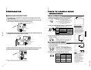
HOW TO HANDLE BASIC
OPERATIONS
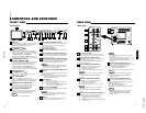
BASIC OPERATION
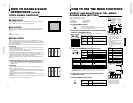
PICTURE ADJUSTMENT
1. Press the main power switch to turn on the power.
2. Press the POWER switch to turn on the power.
ON :Power turns ON. (Power indicator: lit)
Green :The main power is ON, and the monitor’s
power is ON (in the normal operation mode).
OFF :Power turns OFF. (Power indicator: unlit)
Orange :The main power is ON, but the monitor’s
power is OFF (in the standby mode)
Unlit :The main power is OFF.
3. Press the INPUT SELECT buttons to choose input.
Select video/audio signals input to terminals on the rear
panel. The selected button lights in green.
4. Press the VOLUME/SELECT buttons to adjust the
speaker volume.
Press this button to display the speaker volume level on the
screen.
+ : The Built-in speaker volume is increased. (00 = 50)
– : The Built-in speaker volume is decreased. (50 = 00)
* Screen indication will disappear about 10 seconds after operating.
* The on-screen display goes off when you press MENU button.
1. Press select buttons corresponding to the item
you want to adjust.
The item you select is displayed on the screen.
1
Chorma control : Press the CHROMA/PHASE button once.
2
Phase control : Press the CHROMA/PHASE button twice.
3
Contrast control : Press the CONTRAST/BRIGHT button once.
4
Brightness control: Press the CONTRAST/BRIGHT button twice.
*Pressing the CHROMA/PHASE button and CONTRAST/BRIGHT button
alternately while the item is shown on screen restores the previous status.
When no item is shown on screen, CHROMA and CONTRAST have priority.
*Screen indication will disappear about 10 seconds after operating.
*The on-screen display goes off when you press MENU button.
About the STATUS indication
● With the COLOR SYSTEM setting set
to AUTO mode, when you turn on the
power or select inputs, the color
system indication appears for about
3 seconds on the screen while PAL or
NTSC signals are being detected.
It does not appear when receiving a
B/W signal or when no signal is input.
Refer to page 11 for more information
about COLOR SYSTEM setting and
page 12 for more information about
STATUS indication setting.
Notes:
● Phase control is effective only in the
NTSC color system mode.
● Chroma control is not effective when
receiving RGB and B/W or when no
signal is input. (Except when a
component signal is input.)
● When CHROMA is adjusted to “–40,”
the picture becomes less colorful.
● “NO EFFECT” is displayed (for about
3 seconds) when your selected
function has no effect.
● To change the display position on
screen, set UPPER or LOWER with
ADJ. BAR POSI.
2. Adjust with the VOLUME/SELECT buttons.
+
–
9
POWER
INPUT SELECT
SLOT
AB
CD
VOLUME/SELECT
CHROMA
PHASE BRIGHT
CONTRAST
VOLUME/SELECT
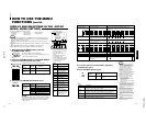
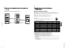
Terminals on the rear panel
Video signal input Audio signal input
1
Input A
VIDEO A terminal AUDIO A terminal
(VIDEO)
2
Input B
VIDEO B terminal
AUDIO B terminal
(VIDEO/Y/C)
PHASE : 00
UPPER
LOWER
VIDEO B (Y/C) terminal
3
Input C
4
Input D
Refer to page 7 for details about the input terminals
on each card and the INPUT SELECT button.
Note: The Y/C (S-video) terminal has priority.
VIDEO A
REMOTE
SLOT
VIDEO B
IN OUT
IN
IN
OUT
Y/C
VIDEO A
REMOTE
SLOT
VIDEO B
IN OUT
IN
IN
OUT
Y/C
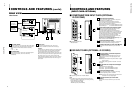
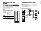
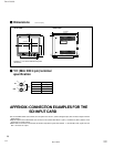
1. Turn off the Color Video Monitor’s main power and unplug the power cable
from the AC outlet.
2. Unscrew the screws and remove the slot cover from the slot (on the rear side
of the monitor) in which you are going to install the card.
3. Insert the Input Card’s board (green-colored) into the slot, fitting the board into
the guide rails on the top and bottom of the slot.
4. Push the Input Card in so that its front panel touches the monitor’s rear panel.
5. Secure the Input Card by replacing the screws removed in Procedure 2.
Ⅵ INSTALLING THE INPUT CARD
Slot cover
Fit the board to
the guide rails.
Rear side of the TM-H1750CG
color video monitor
Knob
Input card (the illustration
shown is of the IF-C01COMG)
Guide rails
Knob
NOTE:Do not touch the terminal connected to the monitor or board pattern.
Do not remove slot covers from the monitor’s slots if they are not in use.
PREPARATION
8
VIDEO A
REMOTE
SLOT
VIDEO B
IN OUT
IN
IN
OUT
Y/C