


Description of Functions
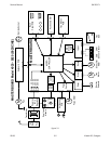
Power Supply
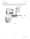
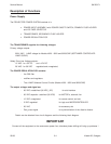
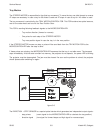
The PROJECTOR POWER SYSTEM consists of a
• POWER INPUT ASSEMBLY with POWER ON/OFF SWITCH, PRIMARY FUSE HOLDER
and VOLTAGE SELECTOR
• TRANSFORMER, SECONDARY FUSE HOLDER
• POWER REGULATION PCB
The TRANSFORMER supplies the following voltages:
Primary voltage outputs:
92/81 VAC LAMP voltage for Models 4020 - 9020 and 9020/CINE (SOFTWARE CONTROLLED
LAMP CURVE)
Safety Extra Low Voltage outputs:
10 VAC for +5V DC and +12V DC
26 VAC for 36 VDC regulated and unregulated,
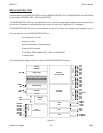
The POWER REGULATION PCB contains:
- line EMI filter
- rectifiers and regulators
- Triac LAMP Software Control Circuits (Models 4020 - 9020 and 9020/CINE)
The output voltages and signal are:
- 36 VDC unstabilized (36 VDC_12P) for slot interface
- 36 VDC capacitor- stabilized (36 VDC) for MOTOR´s, solenoid, fan
- 12 VDC unregulated for remote control and slot
- 5 VDC regulated for logic and MICROCONTROLLER
- 26 VAC for accessory slot
- Zero_cross signal for synchronization of the dissolve feature
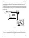
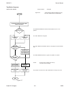
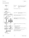
Details can be obtained from circuit diagrams and the following block diagram.
IMPORTANT
Connect all the equipment to the same same power line, otherwise phase shifting will bring up problems !
Service Manual SM 2547-1
03/98 3-4 Kodak AG, Stuttgart