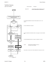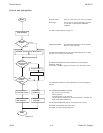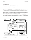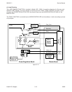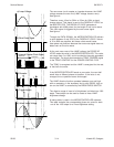
The zero-cross circuit creates an impulse whenever the LAMP
voltage crosses the zero line (LAMP voltage close to zero).
Seefigureb.
Therefore, every 10ms for 50Hz or 8,3ms for 60Hz a signal
change occurs. This signal is sent to the DISSOLVE LOGIC on
the MASTER PCB. The DISSOLVE LOGIC generates a
clocksignal with 4096 pulses for the length of half a sine wave.
This clock signal is triggered by the zero-cross signal.
Seefigurec.
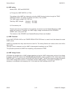
Through the DATA SIGNAL, the MICROCONTROLLER delivers
a value between 3 and 3700 to the DISSOLVE LOGIC. Values
of 0 to 4096 are possible, but these valves would cause
false phase cut positions because the zero-cross signal does not
detect zero on the sine wave.
At the next zero-cross of the LAMP voltage, the DISSOLVE
LOGIC reads the value in the MICROCONTROLLER. This value
can range from 0 to 1000, and is counted by internally generated
clock signal. The clock signal sends the TRIAC TRIGGER signal
to the TRIAC CONTROL on the POWER CONTROL PCB.
The TRIAC is energized and the LAMP is energized for the rest
of that half sine wave.
If the MICROCONTROLLER sends a new value, the next half
would have a different phase cut position. If the value is not
changed, the cut position leaves unchanged.
The LAMP dissolve function operates between zero and high
with an accessory in the accessory slot or with RS232. High or
low on the LAMP is controlled by the BRIGHTNESS SWITCH.
The dissolve range of zero to full brightness is divided into 1000
steps. These steps can be used to create a linear LAMP
brightness change.
A lookup table is used in the MICROCONTROLLER software.
This table contains the corresponding phase cut value for each
one of the 1000 steps for a linear brightness setting.
4096 Pulses
a) Lamp Voltage
b) Zero-Cross Signal
4096 Pulses
c) Internal Counter Clock Signal
d) Example
1000
0
0
1000
e) Trigger Impuls
d) Actual Lamp Voltage
figure 3-11
Service Manual SM 2547-1
03/98 3-14 Kodak AG, Stuttgart


