


Replacements and Installations
SM4530-1 – 30APR96 15
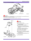
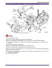
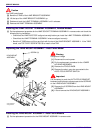
Replacing the CAM STACK ASSEMBLY and CYCLE LEVER ASSEMBLY
Warning
Dangerous Voltage
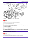
[1] Disconnect the main power.
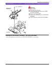
[2] Do the replacement procedure for the MECHANISM ASSEMBLY.
[3] Remove the INDEXER LEVER ASSEMBLY from the TOP PLATE of the MECHANISM ASSEMBLY.
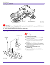
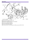
[4] Remove the
Torx
SCREW (on N.P. models) (or Hex SCREW on Painted Models) from the WORM PULLEY
ASSEMBLY.
[5] Remove the WORM PULLEY ASSEMBLY.
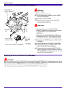
[6] Remove the DIRECTION LEVER LINK from the DIRECTION LEVER.
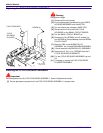
[7] Remove the DIRECTION LEVER SPRING from the DIRECTION LEVER.
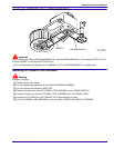
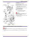
[8] Disconnect the LIFT LEVER SPRING from LIFT LEVER on the TOP PLATE of the MECHANISM ASSEMBLY.
[9] Remove the RETARD SPRING.
[10] Remove the 7
Torx
SCREWS (on N.P. models) (or Hex SCREWS on Painted Models) from the TOP PLATE of
the MECHANISM ASSEMBLY.
[11] Remove the TOP PLATE.
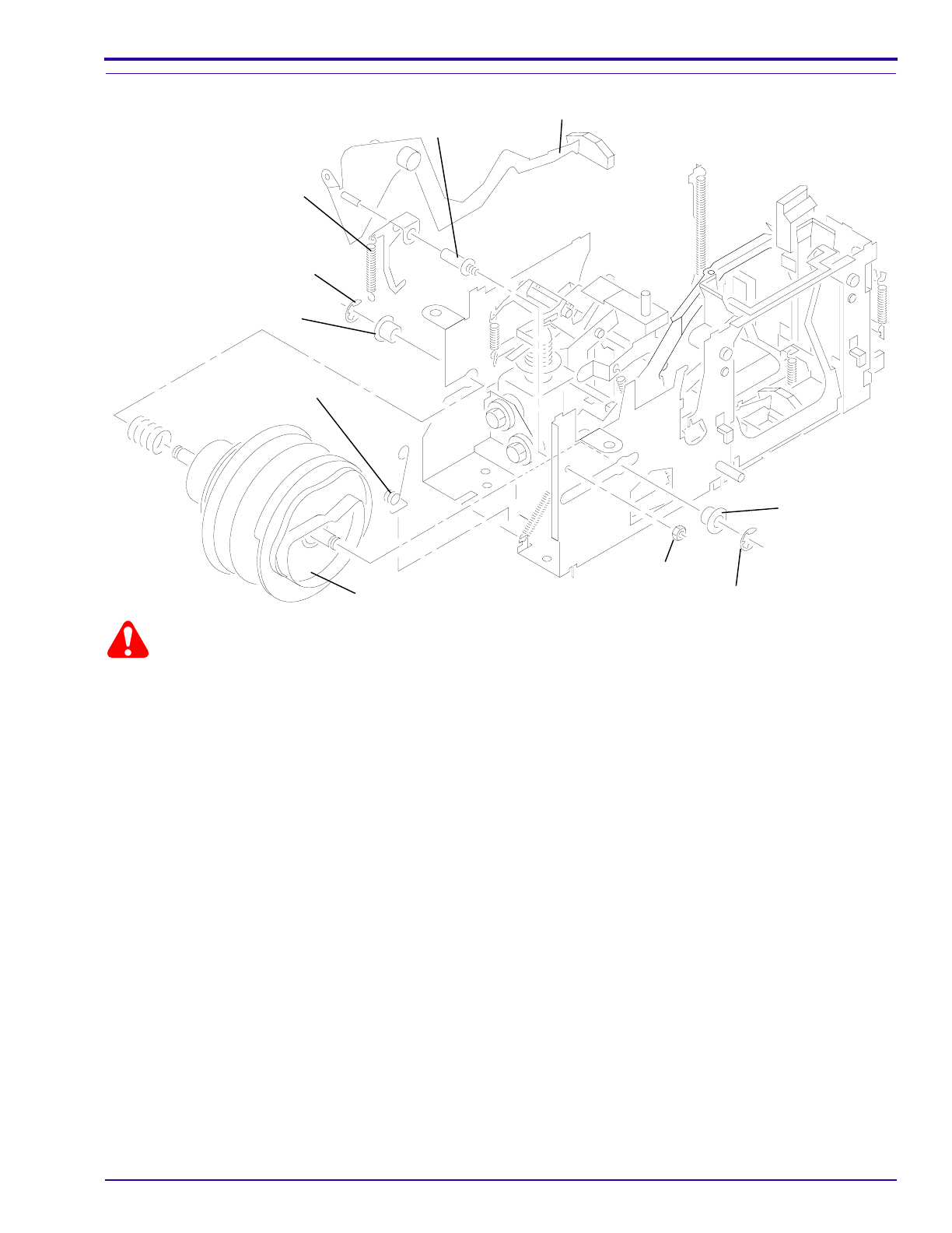
A008_0173HA
A008_0173HCA
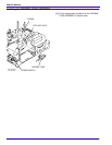
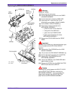
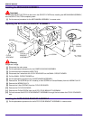
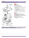
SPRING
RETARD
STYLE 2
BEARING
E-RING
SPRING
RETARD
STYLE 1
SHAFT
LIFT LEVER
LIFT LEVER
BEARING
E-RING
NUT
CAM STACK ASSEMBLY