


2
1
AUDIO IN
1
COMPOSITE IN
2
3
3
COMPOSITE
SUB OUT
RGB IN
65
4
5
6
7
7
AUDIO SUB OUT
COMPONENT IN
SERIAL 1
RGB SUB OUT
SERIAL 2
CAT5 OUT2
CAT5 OUT1
A
B
C
D
E
F
OPTION OUT
PARALLEL REMOTE
POWER
CON
T
DC16V IN
FG
4
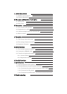
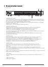
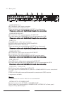
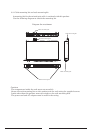
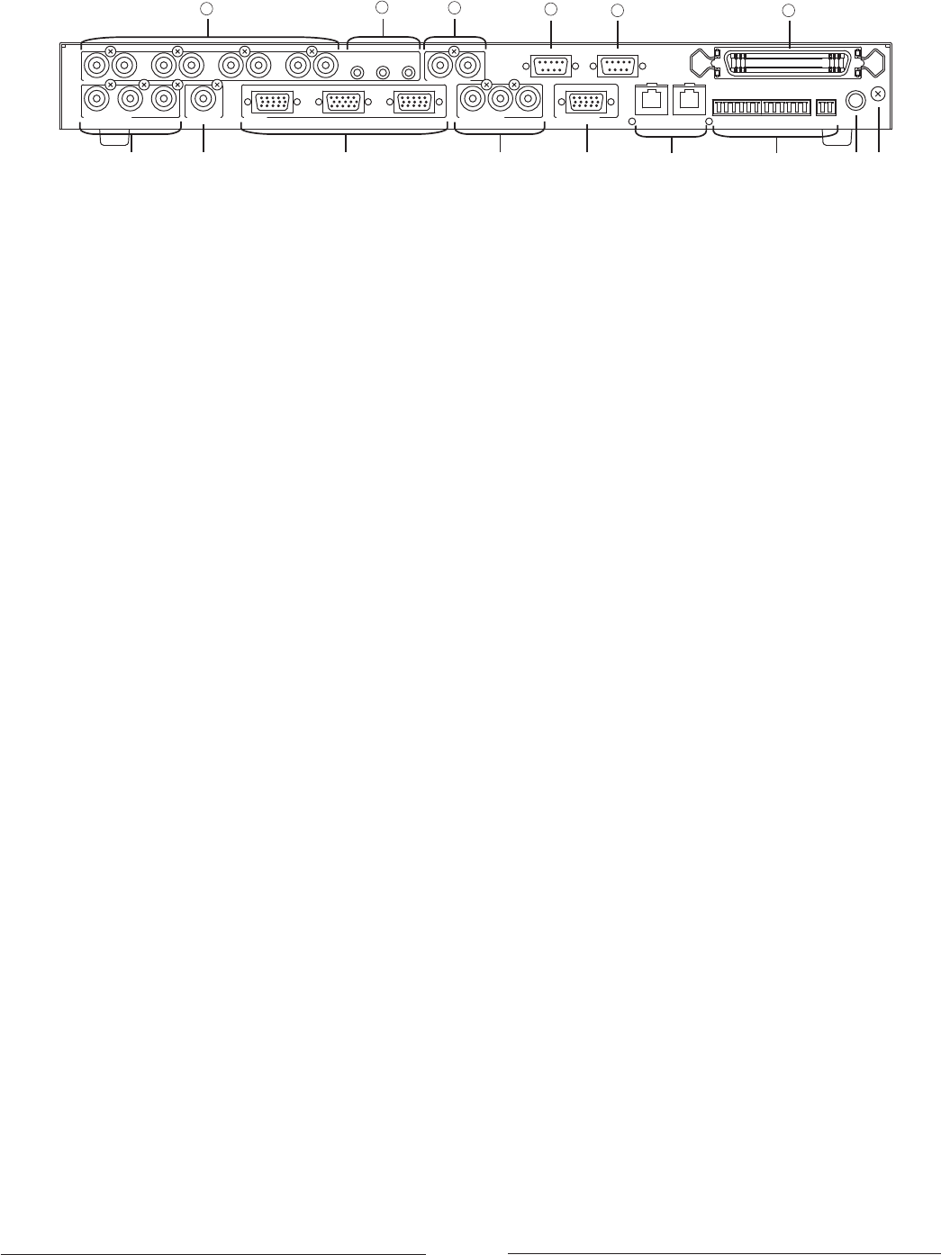
2-2 Rear panel
COMPOSITE IN 1-3
RCA connector, video input connectors.
Input connectors for composite video.
These connectors are corresponding to INPUT 1-3 at front panel.
Please use a cable under 3m(9.84feet) in length when connecting.
COMPOSITE SUB OUT
RCA connector, video output connector for SUB OUT.
The video inputs into COMPOSITE IN can be transmitted to SUB .
Please use a cable under 3m(9.84feet) in length when connecting.
RGB IN 5-8
15pin HD female, video input connector.
For RGB video input connector (not for GonSYNC).
RGB IN 8 is located at front panel .
These connectors are corresponding to INPUT 5-8 on front panel.
Please use a cable under 3m(9.84feet) in length when connecting.
COMPONENT IN 4
RCA connector, video input connector for SUB OUT.
For component video input connector.
These connectors are corresponding to INPUT 4 on front panel.
Please use a cable under 3m(9.84feet) in length when connecting.
RGB_SUB_OUT
15pin HD female, video output connector for SUB OUT.
The video input to RGB IN or COMPONENT IN can be transmitted to SUB.
Please use a cable under 3m(9.84feet) in length when connecting.
CAT5_OUT1 CAT5_OUT2
RJ-45 twisted pair connector for CAT5 OUT.
The video input to COMPOSITE IN, RGB IN or COMPONENT IN can be transmitted
to CAT5.
CAT5e or CAT6 cable connected between this connector and CAT5 receiver.
2 outputs are available.
Warning
Do not connect the receiver which is not recommended.
OPTION OUT A-F, POWER CONT
Terminal connector for OPTION and POWER CONT.
These outputs are corresponding to POWER CONT, OPTION A-F at front panel.
Output is relay (MOS output).