


KRAMER: SIMPLE CREATIVE TECHNOLOGY
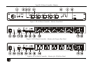
Your PL-50 Power Controller - Monitor
6
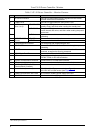
Table 2: PL-50 Power Controller – Monitor Features
#
Feature
Function
1 IR Receiver Window The red LED lights when receiving signals from the Kramer
Infrared remote control transmitter
2 POWER LED The red LED lights when the main power is ON
3 OUT Channel
(from 1 to 5)
STANDBY LED The orange LED lights when the channel outlet is in the
standby mode, and blinks when reading the standby level
4 ACTIVE LED The green LED lights when an outlet is connected to that
power channel and active, and blinks when reading the preset
active level
5 OUT Button Press one or more buttons to select the power channel for
calibrating
6 PRESET LEVEL
Buttons
STANDBY Press to read the standby mode
7 ACTIVE Press to read the active mode
8 PROGRAM USB connector For configuring and programming the unit
9 ETHERNET Connector Connects to the PC or other Serial Controller through computer
networking
10 RESET Press to reset the standby and active values for all the
channels, as well as the security passwords
11 RS-232 9-pin D-sub Port Connect to the PC or other Serial Controller
12 DIP-switches Program, for technical use only
RS-485 TERM, for RS-485 termination
13 RS-485 Terminal Block Connector Connect to the PC or other Serial Controller
14 RELAY terminal block connector Connect to an alarm or other item (see section 6.1)
15 DIGITAL CONTROL (G, OC
1
Connect to an alarm or other item )
Terminal Block Connector
16 Power Outlets (from 1 to 5) 220-240V AC for European version (see Figure 2)
100-120V AC for USA version (see
Figure 3)
17 POWER IN Connector with FUSE AC connector enabling power supply to the unit
18 POWER Switch Illuminated switch supplying power to the unit
1 OC means Open Collector