


Operating Your PL-50 Power Controller – Monitor
27
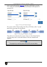
6.4 DIP-switch Settings
Figure 29 and Table 9 define the DIP-switches:
1 2
Table 9: DIP-switch Definitions
DIP
Function:
1 PROGRAM, for factory use only
2
ON for RS-485 Line Termination with 120Ω;
OFF for no RS-485 Line Termination
Figure 29: SETUP DIP-switches
7 Operating Your PL-50 Power Controller – Monitor
You can operate your PL-50 via:
• The front panel buttons
• Remotely, by USB, RS-485 or RS-232 serial commands transmitted by a
touch screen system, PC, or other serial controller
• The Ethernet
• Remotely, from the Kramer Infrared Remote Control Transmitter or the
infrared remote extension cable transmitter
Powering up PL-50 unit, recalls the previous settings (that is, the state of the unit
when it was powered down) from the non-volatile memory.
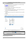
7.1 Calibrating via the Front Panel Buttons
Prior to monitoring the PL-50 outlets, each outlet needs to be measured for its
standby and Active modes.
To set the Active mode, do the following:
1. Press one or more OUT buttons to select the channels for which you want to
measure the standby or active modes.
The selected buttons illuminate.
2. Set the connected units to the Active mode.
3. Press the PRESET LEVEL ACTIVE button.
The selected orange OUT buttons, and their related ACTIVE green LEDs
blink.
4. Press each of the selected orange blinking buttons to initialize the
measurement.
The ACTIVE green LED blinks until measurement is complete.