


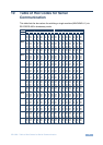
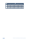
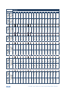

40 VP-1608 - Kramer Protocol 2000
NOTE 12 - Under normal conditions, the machine's present status is saved each time a change is made. The "power-
down" save (auto-save) may be disabled using this code. Note that whenever the machine is turned on, the auto-save
function is set.
NOTE 13 - This is a request to identify the switcher/s in the system. If the OUTPUT is set as 0, and the INPUT is set as
1, 2, 5 or 7, the machine sends its name. The reply is the decimal value of the INPUT and OUTPUT. For example, for a
2216, the reply to the request to send the audio machine name would be (HEX codes):
7D 96 90 81 (i.e. 128dec+ 22dec for 2nd byte, and 128dec+ 16dec for
3rd byte).
If the request for identification is sent with the INPUT set as 3 or 4, the appropriate machine sends its software version
number. Again, the reply would be the decimal value of the INPUT and OUTPUT - the INPUT representing the number
in front of the decimal point, and the OUTPUT representing the number after it. For example, for version 3.5, the reply to
the request to send the version number would be (HEX codes):
7D 83 85 81 (i.e. 128dec+ 3dec for 2nd byte, 128dec+ 5dec for 3rd
byte).
If the OUTPUT is set as 1, then the ASCII coding of the lettering following the machine’s name is sent. For example, for
the VS-7588YC, the reply to the request to send the first suffix would be (HEX codes):
7D D9 C3 81 (i.e. 128dec+ ASCII for “Y”; 128dec+ ASCII for “C”).
NOTE 14 - The number of inputs and outputs refers to the specific machine, which is being addressed, not to the
system. For example, if six 16X16 matrices are configured to make a 48X32 system (48 inputs, 32 outputs), the reply to
the HEX code
3E 82 81 82 (i.e. request the number of outputs)
would be HEX codes
7E 82 90 82
i.e. 16 outputs
NOTE 15 – When the OVR bit (4th byte) is set, then the “video” commands have universal meaning. For example,
instruction 1 (SWITCH VIDEO) causes all units (including audio, data, etc.) to switch. Similarly, if a machine is in
“FOLLOW” mode, it performs any “video” instruction.
NOTE 16 - The reply to the “REQUEST WHETHER PANEL IS LOCKED” is as in NOTE 4 above, except that here the
OUTPUT is assigned with the value 0 if the panel is unlocked, or 1 if it is locked.
NOTE 19 – When data (i.e. the INPUT and/or OUTPUT bytes) of more than 7 bits is required, this instruction is sent
before sending the instruction needing the additional bits. The data in this instruction then becomes the Most Significant
Bits of that next instruction. For example, to set the audio gain (instruction 22) of output 3 to 681dec (2A9hex), you
would first send HEX codes
3F 80 85 81
and then send HEX codes
16 83 A9 81
To set the audio gain of output 6 to 10013dec (271Dhex), first send HEX codes
3F 80 CE 81
followed by HEX codes
16 86 9D 81
NOTE 21 – Instruction 59 and instruction 60 load data for sending to the crosspoint switcher (or for storing in a SETUP),
i.e. the data is “lined-up” to be executed later. Instruction 58 executes the loaded data.
NOTE 22 – If the INPUT byte is set as 127dec, then the data stored in a SETUP is loaded. The SETUP # is in the
OUTPUT byte.
NOTE 23 – Further information needed in instructions 21, 22, 25 and 26, is sent using instruction 42 – which is sent
prior to the instruction. For example, to request the audio gain value of right input # 9, send hex codes
2A 84 80 81
and then send HEX codes
19 89 81 81