


Kramer Electronics Ltd.
7
6 ABOUT THE VIDEO SCALER
The Video Scaler is controlled via the Front Panel Buttons and its status determined by the Front Panel LED
indicators. The VP-722DS may also be controlled via an external control device connected to its RS-232 port,
which will be covered later in this manual.
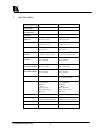
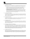
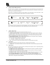
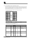
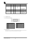
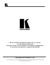
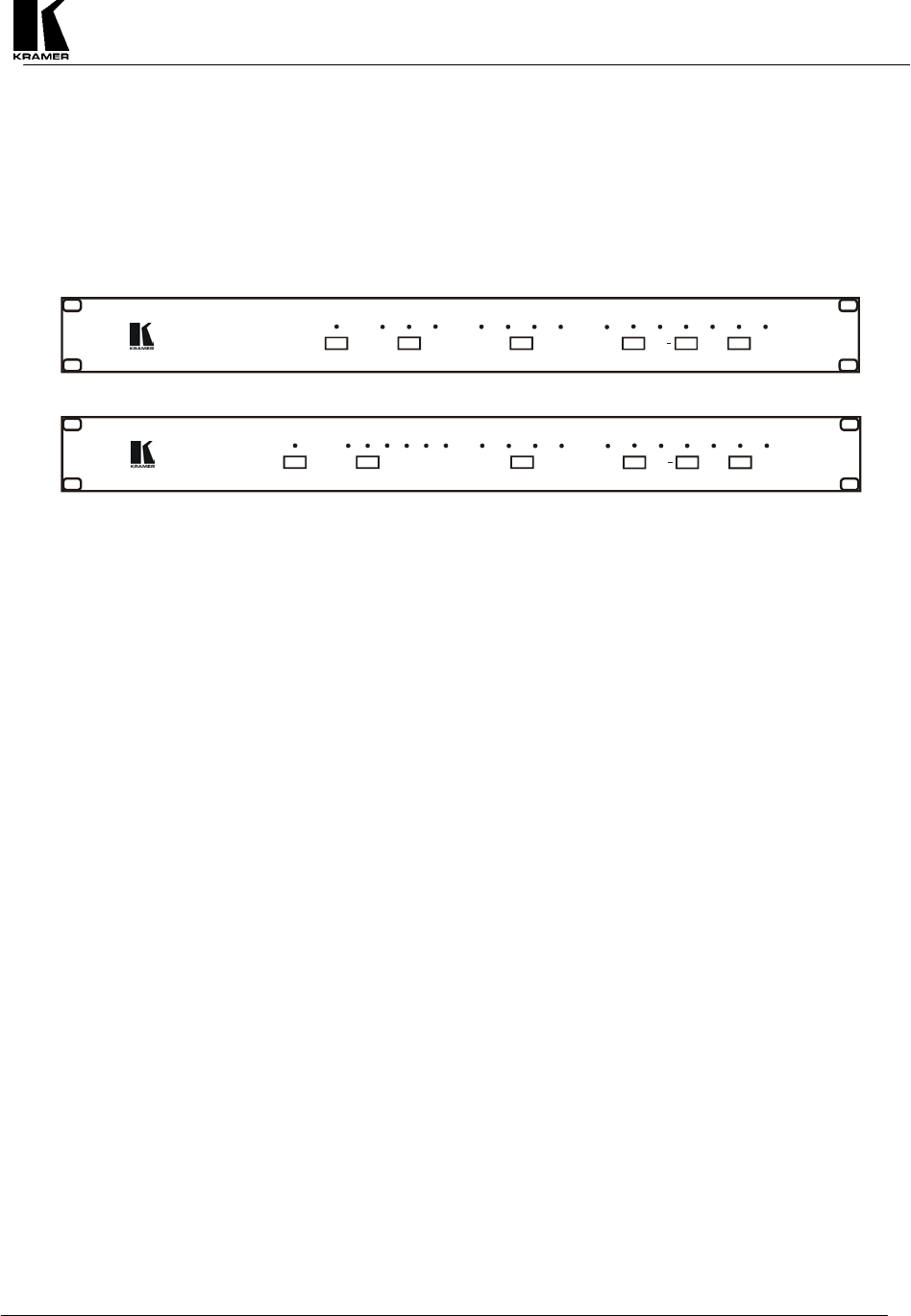
Shown below are diagrams that indicate the main features of the Front Panels of the Video Scalers. Both
models covered by this manual appear similar and their basic operation is identical.
-------------
+
SHARP
CONTCOLOR
BRIGHTHUEHORIZBYPASSVGAPC SVGA
XGA
OUTPUT
INPUT
SV CVAUTO
SELECT
VERT
VP-721DS
Digital Video Scaler
-------------
+
SHARP
CONTCOLOR
BRIGHTHUEHORIZBYPASSVGA SVGA
XGA
OUTPUT
PC1 PC2
PC3
PC4
INPUT
SV
CVAUTO
SELECT
VERT
VP-722DS
Digital Video Scaler
This following sections go through the Front Panel Buttons and what control they provide over the Video
Scaler. It also provides information on the Status Indications given by the Front Panel LED’s.
7 INPUT SELECTON
The Video Scaler’s Input can be chosen from the Front Panel in two ways:
Automatic Input Select Mode - the Video Scaler determines when a video signal is present at either the
Composite Video or S-Video input connector and automatically selects that as the active input. If a signal is
present at both inputs, priority is given to the S-Video input. E.g., this feature allows input selection to be
done by switching power on or off to the source video devices.
Manual Input Select Mode - allows manual selection of which input video signal is chosen. Repeatedly
pressing the button toggles through the available inputs:
a) VP-721DS = Composite Video, S-Video or PC.
b) VP-722DS = Composite Video, S-Video, PC1, PC2. PC3 or PC4.
Note – The PC Inputs are simply pass-through connections to the output and are not scaled.
7.1 Auto Button
Pressing the Auto Button places the Video Scaler in the Automatic Input Select Mode.
AUTO LED – The Auto Button illuminates when the Video Scaler is in the Automatic Input Select Mode.
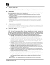
7.2 Input Button
Pressing the Input Button allows manual selection of which input video signal is chosen. Repeatedly pressing
the button toggles through the available inputs:
SV LED - The SV LED is illuminated when the S-Video input has been chosen by repeatedly pressing the
Input Button until that source has been selected.
CV LED - The CV LED is illuminated when the Composite Video input has been chosen by repeatedly
pressing the Input Button until that source has been selected.
PC LED (VP-721DS) - The PC LED is illuminated when the Bypass Mode has been chosen by repeatedly
pressing the Input Button until that source has been selected. The Bypass LED also illuminates.
PC 1, PC2, PC3, PC4 LEDs (VP-722DS) - The PC1, PC2, PC3 or PC4 LED is illuminated when the
Bypass Mode has been chosen by repeatedly pressing the Input Button until the corresponding PC Input has
been selected. The Bypass LED also illuminates.