


KRAMER: SIMPLE CREATIVE TECHNOLOGY
Your VP-727T Presentation Switcher Control Panel
6
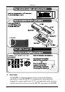
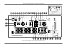
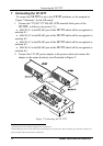
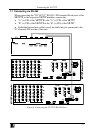
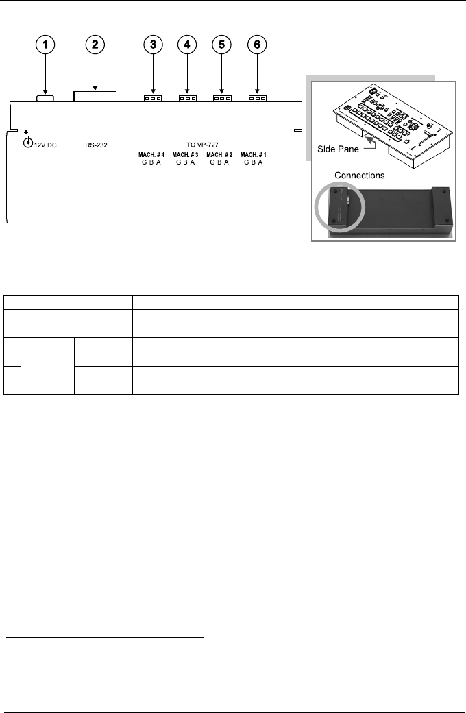
Figure 2 and Table 2 define the side panel of the VP-727T:
Figure 2: VP-727T Presentation Switcher Control Panel (Side Panel)
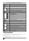
Table 2: VP-727T Presentation Switcher Control Panel (Side Panel) Features
#
Feature Function
1 12V DC +12V DC connector for powering the unit
2 RS-232 DB 9 Connector Connects to the PC for upgrading the firmware
3 MACH. # 4 Connects to the RS-485 port
1
on the VP-727 which is recognized as machine # 4
4 MACH. # 3
Connects to the RS-485 port
1
on the VP-727 which is recognized as machine # 3
5 MACH. # 2
Connects to the RS-485 port
1
on the VP-727 which is recognized as machine # 2
6
TO VP-727
3-PIN
Terminal
Block
MACH. # 1
Connects to the RS-485 port
1
on the VP-727 which is recognized as machine # 1
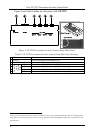
1 Pin G is for the Ground connection, which is sometimes connected to the shield of the RS-485 cable. In most applications,
the ground is not connected; pins B (-) and A (+) are for RS-485. The RS-485 PINOUT: GBA may not be printed on some
VP-727T units