


Digital Display Wall Clock Guide Page 8
When used as a RS485 clock, the master clock will send a signal to the wall clock every minute. The 9-
Volt alkaline battery (not included) is optional in these types of installations.
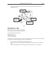
Battery Installation - DDC2 / DDC4 Series
DDC2
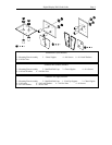
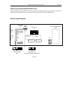
Remove the four phillips head screws from the left or the right end cap and remove. Slide the lens and
circuit board assembly out of the case. Place the lens aside and carefully flip the circuit board assembly
over and lay it face down on a clean, smooth work surface. Locate the Battery Cradle on the upper right
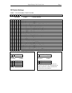
corner of the circuit board assembly. (See figure 2, page 9) Slide the battery into the cradle making sure the
Positive and Negative connections of the battery and cradle match. Snap the battery onto the connections
located inside the battery cradle. Slide the lens and circuit board assembly back into the case, replace the
end cap and secure with the four phillips head screws.
DDC4
Remove the two phillips head screws from the left or the right end cap and remove. Slide the front panel
assembly out of the case. Carefully flip the front panel assembly over and lay it face down on a clean,
smooth work surface. Locate the Battery Cradle on the upper right corner of the circuit board assembly.
(See figure 2, page 9) Slide the battery into the cradle making sure the Positive and Negative connections of
the battery and cradle match. Snap the battery onto the connections located inside the battery cradle. Slide
the front panel display back into the case, replace the end cap and secure with the two phillips head screws.
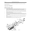
Power Cord Installation - DDC2/4-RS
Note: This section refers only to the 115VAC models. Applying power other than 24VAC to models DDC2-
RS-24 or DDC4-RS-24 WILL CAUSE DAMAGE and void the warranty. See Appendix B for proper wiring
of these models.
DDC2-RS
Remove the four phillips head screws from the left or the right end cap and remove. Slide the lens and
circuit board assembly out of the case. Place the lens aside and carefully flip the circuit board assembly
over and lay it face down on a clean, smooth work surface. Remove one of the vent caps from the case of
the wall clock and route the power cord through it to the back of the circuit board assembly. (If the power
cord will be routed through the back-of-the-clock conduit access, route the cord through the gang box and
conduit access hole to the back of the circuit board assembly). Strip away 1/2" of the protective shield from
each wire of the power cord. Locate the two black wires leading from J1 (see figure 2, page 9) and attach
the AC In line of the cord to one and the AC Return line to the other. (normally black is AC In and white is