


Digital Display Wall Clock Guide Page 12
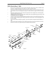
» Slide the lens and circuit board assembly back into the case, replace the end cap and secure with
the four phillips head screws.
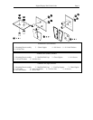
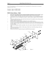
DDC4
» After deciding the location where the clock will be mounted, make two marks 12" apart and
horizontal.
Note: If mounting near a ceiling, make sure the holes are at least 2 1/4" away from the ceiling.
Note: Make sure you have at least 16" of side clearance on one side in order to remove the front panel.
» Drill a 5/16" hole at each mark
» Insert a wall anchor and tap it flush to the wall with the hammer.
» Insert a screw into each wall anchor leaving 1/4" exposed.
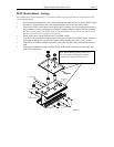
» Remove the two phillips head screws from the left or the right end cap and remove. Slide the front
panel assembly out of the case and set aside.
» Line up the two keyholes on the back of the case and slip over the two screws and tighten
securely. ( The lower mounting holes can be marked at this point, the case removed, holes drilled
and wall anchors installed if so desired)
» Remove the desired vent cap that any required wiring will route through. (If the wiring will be
installed through the back-of-the-clock conduit access, route the fly leads of the clock's Cable
Harness Assembly from the interior of the clock through the hole in the Clock's rear plate. Use
wire nuts or crimp connectors to join these leads with the power and synch signal cable in the
gang box behind the clock to eliminate possible snagging when the circuit board assembly is
removed or replaced. If RS-485 signaling is used, attach the signal pair to the mini Terminal Block
Plug and pass the cable from behind the clock, through the hole into the clock's interior).
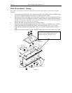
» Route the 6-position plug (and optional RS485 cable) to the circuit board assembly and attach.
» Slide the front panel display back into the case, replace the end cap and secure with the two
phillips head screws.
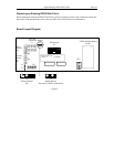
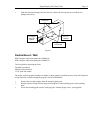
Mounting to a Single Gang Box
Two mounting holes have been located in the center of the case 2 1/4" apart for mounting to a single gang
wall box. A 7/8" hole has been placed between the mounting holes that will accept conduit if desired.
See page 14, figure 3.