


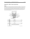
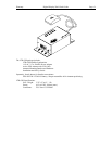
Page 49 Digital Display Wall Clock Guide DDC2 / 4-RS -485 Wiring
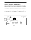
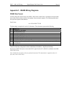
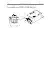
LTR4 / 8-512 to DDC2-RS / 4-RS
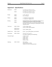
Terminal # Signal Signal JP4 Connection
9 (D-) Transmit Data (-) Transmit Data (-) D-
8 (D+) Transmit Data (+) Transmit Data (+) D+
BLK
BLK
LTR4 / 8-512 Terminal Connections
Cable should be RS232 twisted pair / CAT3 or CAT5 type.
Maximum distance to last DDC Clock is 4000 feet.
Last DDC Clock must have jumper installed on position J2.
See page 8 for details.
7
8
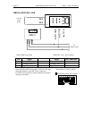
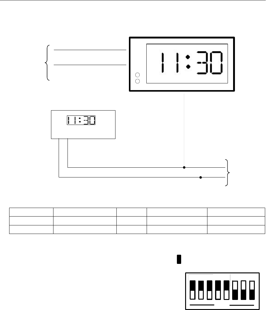
Set switches 1-5 of S1 as shown.
Indicates depressed side of switch
OPEN
1
2
3 4 5
6
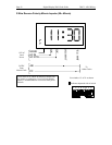
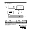
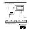
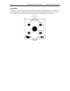
DDC2-RS / 4-RS - JP4 Connector
To
Other Clocks
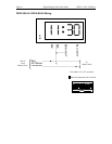
LTR4 / 8-512
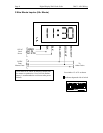
11 30
:
D+
D-
H
M
D- of JP4
D+ of JP4
115VAC
Local
Powe
r