


LTRx-512 Installer’s Guide
8
Note: UL regulations require that you do NOT place high voltage (120V) and low
voltage communication cables in the same conduit or through the same knockout holes
•
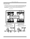
Follow the wiring steps in the next chapter
•
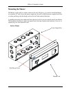
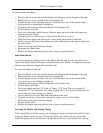
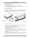
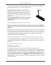
For the cleanest installation, mount the display unit over a standard “double gang” 4-inch
electrical box
•
Route the other end of the 8-foot connection cable to this electrical box
•
Place two #8 screws, 12 inches apart and level, ½-inch down from the top of the electrical
box
•
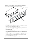
Connect the 8-foot connection cable and any communication cables to the display unit
•
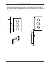
Check your connections, then turn your Master on using the On/Off switch on the power
supply board
•
Attach the furnished cover to the power supply using four 6-32 screws (two of these
screws you earlier removed from the display unit)