


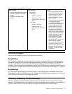

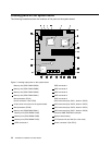

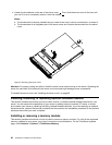
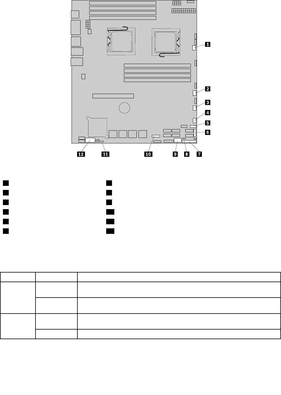
Figure6. Locating other connectors on the system board
1 System fan 1 connector 7 J35 (for front control cable)
2 System fan 2 connector 8 JP1 (clear CMOS)
3 System fan 3 connector 9 USB 2 connector
4 System fan 4 connector 10 J21 (SGPIO connector for onboard SAS port 5-8)
5 Front USB connector 11 JP7 (set onboard SAS)
6 J51 (SGPIO connector for onboard
SAS port 1-4)
12 J16 (COM2 connector)
The following table introduces the jumper switches on the system board.
Table 7. Jumper settings
Jumper Position Description
Pins 1-2
The default position at which the jumper is placed on pins 1-2 during the normal
operation of the system.
JP1: Clear
CMOS
Pins 2-3
If the jumper is placed on pins 2-3, when the jumper is moved back to the default
positions and at the next startup, the settings of CMOS will be cleared automatically.
Pins 1-2
The default position at which the jumper is placed on pins 1-2 during the normal
operation of the system. The onboard SAS controller is Enabled.
JP7: Set
Onboard
SAS
Pins 2-3
If the jumper is placed on pins 2-3, the onboard SAS controller is Disabled.
Note: Before clearing the CMOS, turn off the server and disconnect the power cord. Move the jumper from
pins 1-2 to pins 2-3. Wait more than ve minutes and then move the jumper back to the normal position
(pins 1-2) to clear CMOS.
Chapter 4. Locating parts, controls, LEDs, and connectors 15