


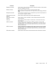
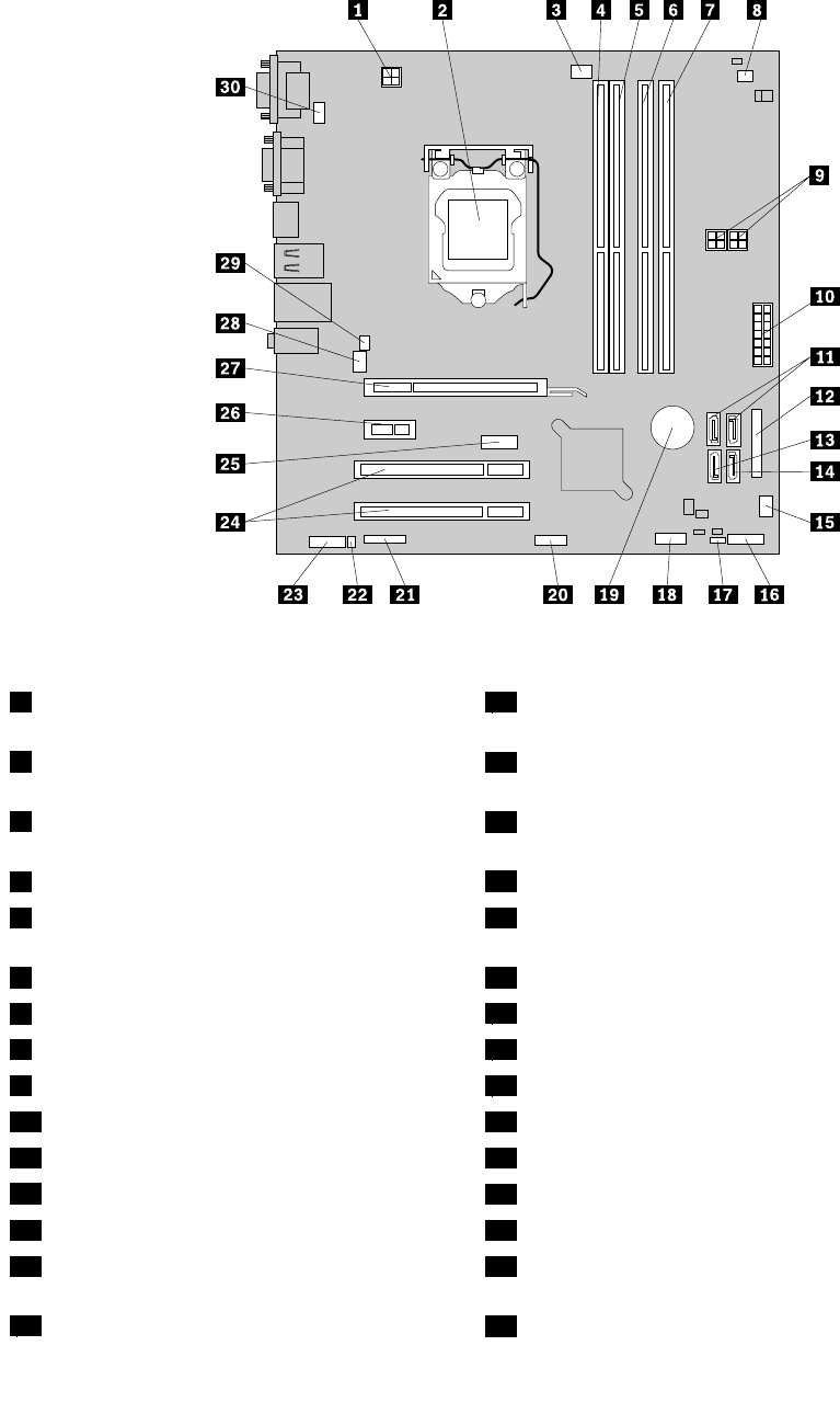
Figure 4 “System board part locations” on page 13 shows the locations of the parts on one type of system
board.
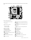
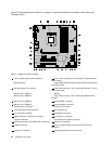
Figure 4. System board part locations
1 4-pin microprocessor power connector
16 Front panel connector (for connecting LED indicators and
power switch)
2 Microprocessor
17 Clear CMOS (Complementary Metal Oxide Semiconductor)
/Recovery jumper
3 Microprocessor fan connector
18 Front USB connector 1 (for connecting USB ports 1 and 2
on the front bezel)
4 Memory slot 1 (DIMM 1)
19 Battery
5 Memory slot 2 (DIMM 2) 20 Front USB connector 2 (for connecting additional USB
devices)
6 Memory slot 3 (DIMM 3) 21 Serial (COM2) connector
7 Memory slot 4 (DIMM 4)
22 Internal speaker connector
8 Thermal sensor connector 23 Front audio connector
9 4-pin SATA power connectors (2) 24 PCI card slots (2)
10 14-pin power connector 25 DisplayPort connector
11 SATA connectors 1 and 2 (SATA 3.0 connectors) 26 PCI Express x1 card slot
12 Parallel connector
27 PCI Express x16 graphics card slot
13 eSATA connector 28 System fan connector
14 SATA connector 3 (SATA 2.0 connector) 29 Cover presence switch connector (Intrusion switch
connector)
15 Power fan connector
30 PS/2 keyboard and mouse connector
Chapter 1. Product overview 13