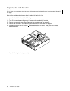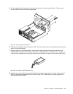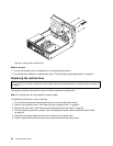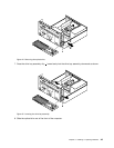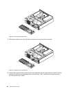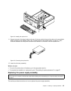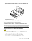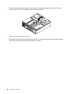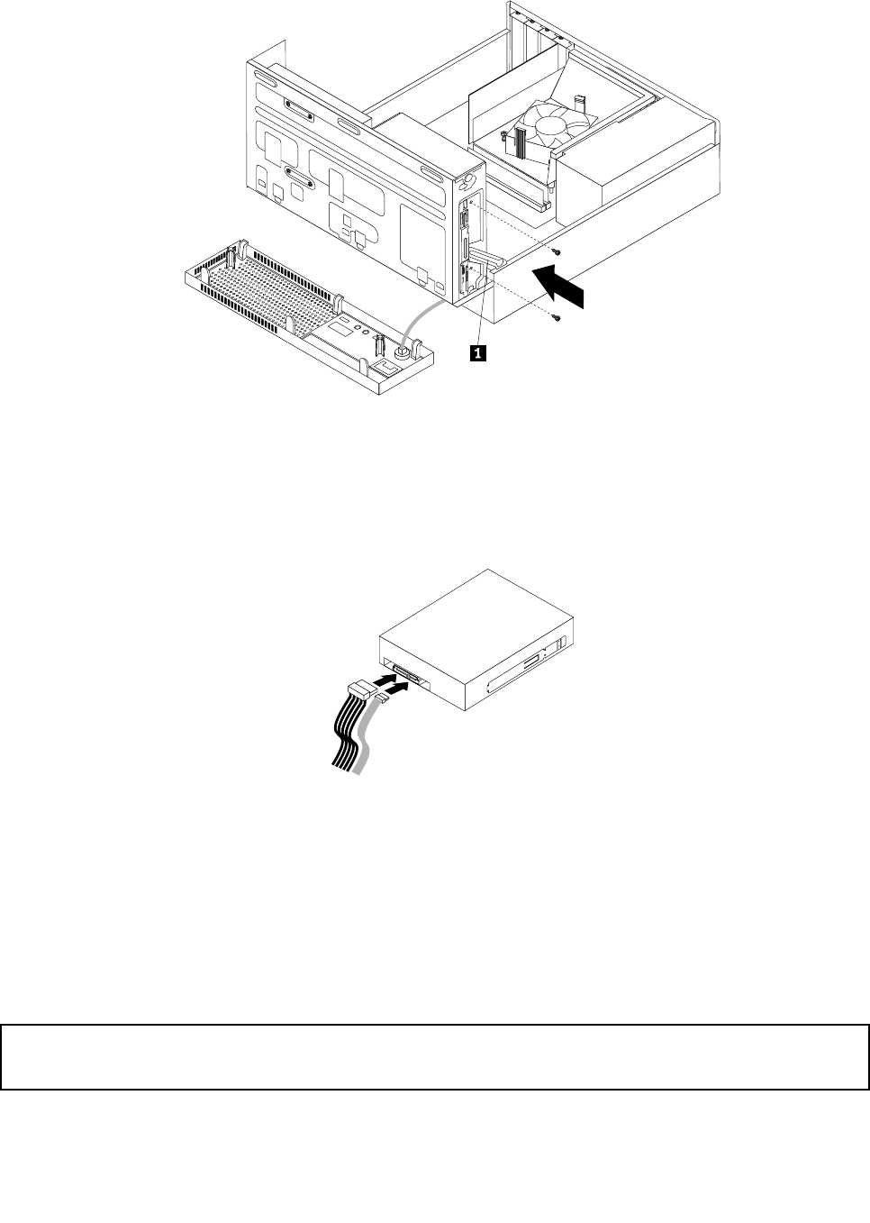
Figure28. Installing the optical drive
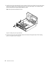
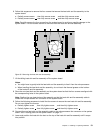
11. Connect one end of the signal cable to the rear of the new optical drive and the other end to an available
SATA connector on the system board. See “Locating parts on the system board” on page 12. Then,
locate an available ve-wire power connector and connect it to the rear of the new optical drive.
Figure29. Connecting the optical drive
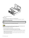
12. Lower the drive bay assembly.
What to do next:
• To work with another piece of hardware, go to the appropriate section.
• To complete the installation or replacement, go to “Completing the parts replacement” on page 67.
Replacing the power supply assembly
Attention:
Do not open your computer or attempt any repair before reading and understanding the “Important safety information”
on page v
.
This section provides instructions on how to replace the power supply assembly.
Chapter 5. Installing or replacing hardware 45


